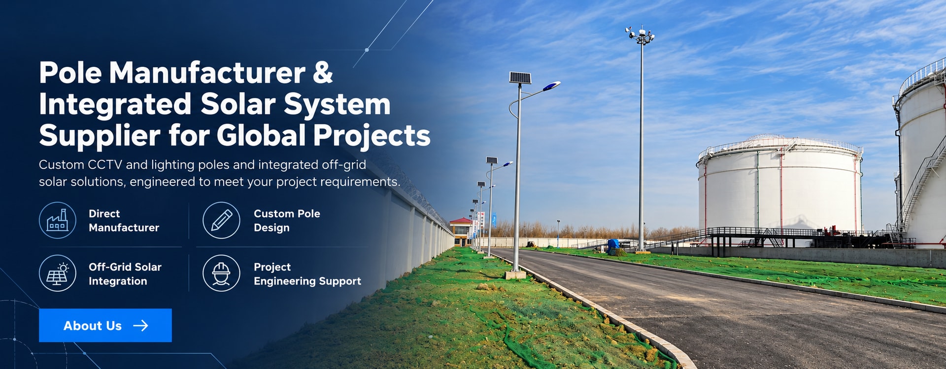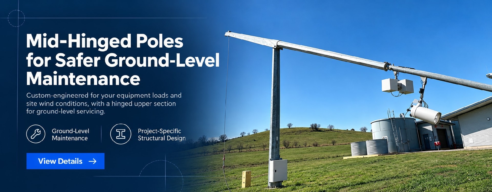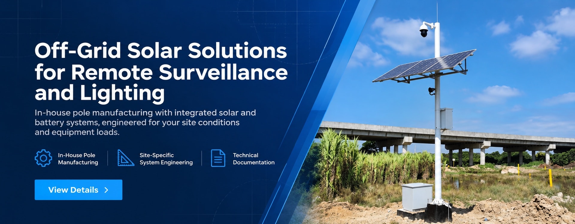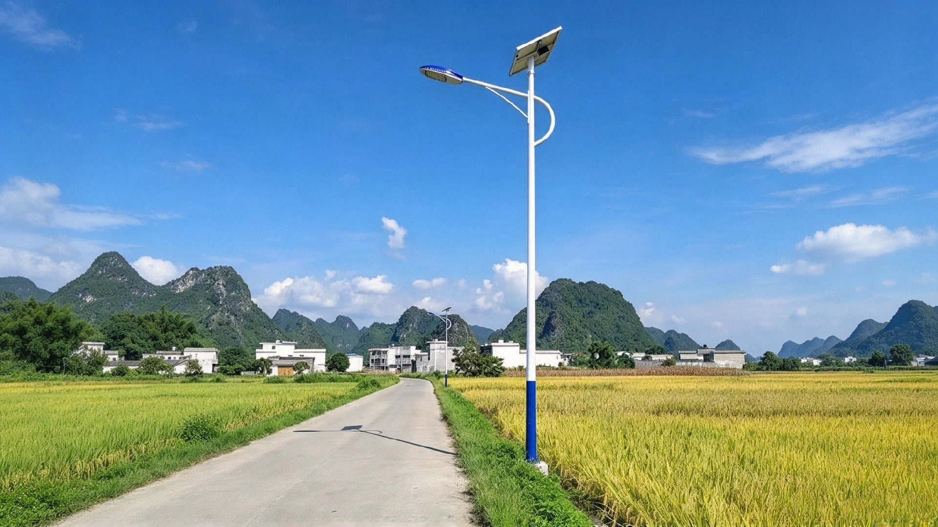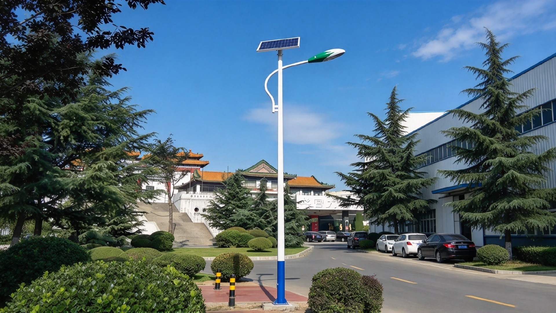
Custom pole structures for customer-supplied solar lighting systems.
Designed for roads, industrial sites, parking areas, and remote facilities. Pole structures, base plates, and mounting interfaces are tailored to the installation height, equipment dimensions, weight, mounting positions, and project wind loads, helping integrators accommodate their own lighting and solar power equipment.
Custom Pole Design | Equipment Interface Compatibility | Cable Routing Provisions | Outdoor Corrosion Protection
Pole Design Matched to Your Equipment
Pole selection for solar lighting applications must account for the combined weight and wind-exposed area of the luminaires, solar panels, and mounting brackets.
Using customer-provided equipment specifications and layout requirements, we determine the pole cross-section, wall thickness, connection positions, and foundation interfaces to reduce equipment fit-up issues and on-site modifications.
Structure Designed for Project Loads
Pole structures are configured according to height, equipment weight, solar panel wind area, and site wind load requirements. Each equipment configuration is assessed individually rather than selecting the pole by height alone.
Coordinated Mounting Interfaces
Connection points can be prepared to match customer-supplied lighting arms, solar panel brackets and other mounting hardware, simplifying subsequent assembly.
Cable Routing and Maintenance Access
Cable entry openings, access doors and earthing connection points can be provided to suit project requirements, reducing on-site drilling and modifications.
Project-Specific Materials and Corrosion Protection
Carbon steel, stainless steel and aluminium options can be assessed against structural requirements, site conditions and budget.
Carbon steel poles can be hot-dip galvanized, with an additional protective coating where specified. Material grades and surface treatments are confirmed for each project
Customization Options
| Item | Available Configuration |
| Height | Matched to the lighting layout and site requirements |
| Material | Selected according to structural and environmental requirements |
| Pole Shape | Circular, tapered, or polygonal |
| Structural Dimensions | Pole diameter, wall thickness, and section connection details |
| Mounting Interfaces | Prepared to match customer-supplied components |
| Foundation Interface | Base plate dimensions and anchor bolt hole pattern |
| Cable Routing and Access | Cable entries, access doors and earthing connection points |
| Surface Finish | Corrosion protection, coating and colour |
Scope of Supply
Pole structure only.
Solar panels, luminaires, batteries, controllers, cables and other electrical components are excluded. Lighting arms, solar panel mounting brackets, enclosures and other accessories are also outside the scope of supply described on this page.
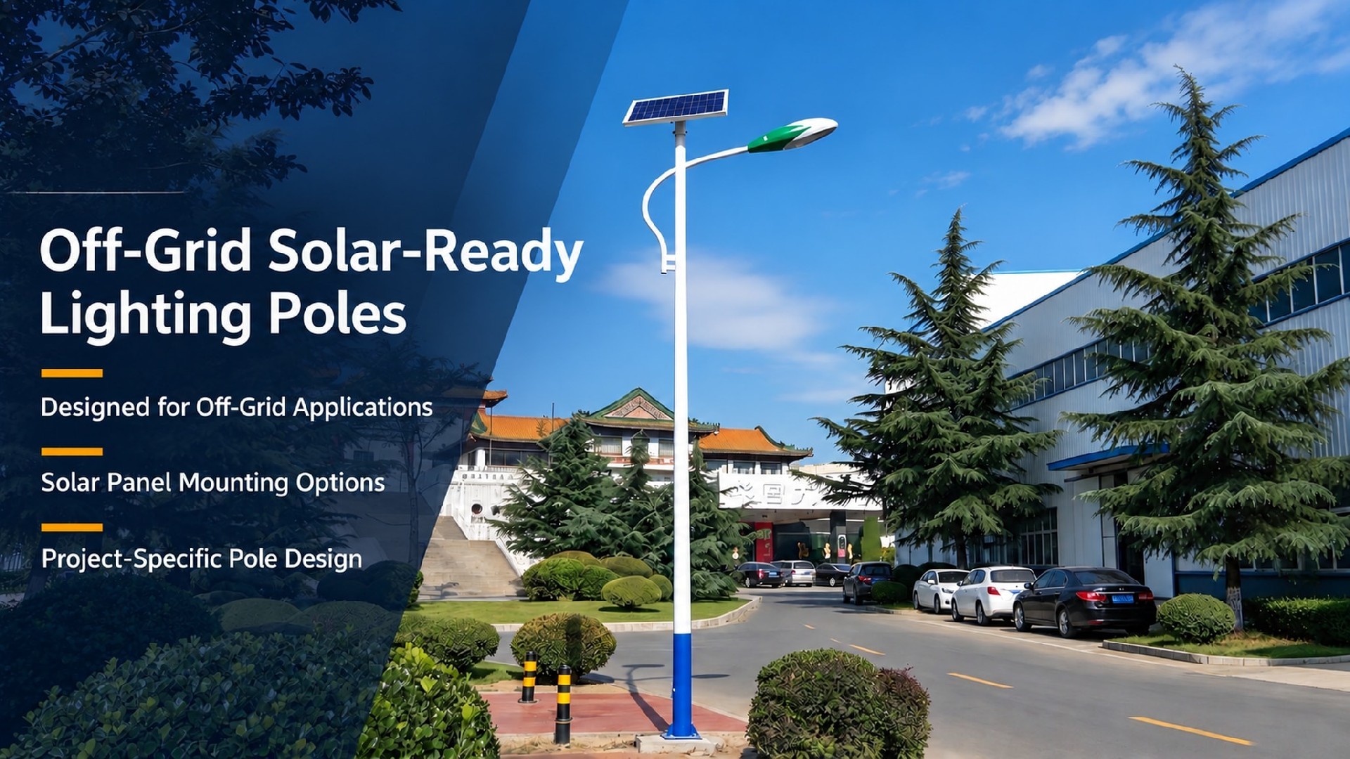
Images illustrate solar lighting applications. Solar panels, luminaires and other equipment shown are for application reference and are not supplied with the pole.
Please provide the project location, quantity, pole height, equipment dimensions and weights, mounting layout, connection details, and wind load requirements.
We will use your equipment specifications and site conditions to propose a suitable pole structure and manufacturing configuration.
Jump to : Commercial Terms | FAQ | Delivery Commitment
Supported by an ISO 9001:2015 quality management system, we can adapt pole design, manufacturing quality control, corrosion protection, and technical documentation to project-specific standards and local requirements, supporting overseas project approval, procurement, and acceptance.
Structural Design & Wind Load Verification: Structural calculations can be performed in accordance with EN 40 / EN 1993, AASHTO, applicable AS/NZS standards, SASO requirements, or other project-specified codes. Design verification can incorporate site wind speed, equipment loads, mounting height, and environmental conditions.
Welding & Manufacturing Control: Welding procedures and quality control can be adapted to applicable EN 1090 execution requirements and ISO 3834 welding quality requirements, with corresponding process, inspection, and documentation controls implemented as required by the project.
Corrosion Protection: Hot-dip galvanizing and coating systems can be configured according to the project environment and required service life. Treatments can be specified to ISO 1461, ASTM A123/A123M, or other project requirements for standard outdoor, coastal, high-humidity, and high-salinity environments.
Engineering Documentation Support: Project documentation can include structural calculation reports, shop drawings, material certificates, welding records, galvanizing or coating inspection reports, dimensional inspection records, and factory quality documentation for client, consultant, or EPC review.
Multi-Market Project Support: We support project requirements across Europe, North America, the Middle East, and Asia-Pacific. Applicable design standards, inspection requirements, and document packages can be defined according to the project location and technical specification.
Term | Detail |
| Customization | Supported — MOQ 1 unit |
| Lead time | Standard configuration: 3–4 weeks / Custom-engineered configuration: 4–5 weeks |
| Payment terms | 30% T/T advance · 70% before shipment · L/C at sight accepted |
| Trade terms | EXW: Specify named place FOB: Specify port of shipment CFR / CIF: Specify destination port |
| Inspection support | Third-party factory inspection by SGS / BV / TÜV welcomed |
| Samples | Available — sample cost credited against first production order |
Installation Reminders
⚡ Galvanic Corrosion Prevention: Carefully match fastener materials. When connecting dissimilar metals, use isolating non-conductive gaskets. (Service option: Pre-installed nylon/EPDM isolation gaskets available upon request).
💧 Drainage & Sealing: Keep base drainage openings unobstructed; hand-hole covers and seals must remain intact. Never bury flange plates underground.
🛡️ Surface Protection: Protect passivated and brushed surfaces from mechanical scratches during installation. Local touch-up passivation treatment is required for any damaged areas.
🔌 Grounding Requirement: Complete proper grounding and equipotential bonding in compliance with local electrical codes.
🏗️ Foundation Rules: Anchor bolts and concrete foundations must satisfy local wind-load requirements. Erect poles only after concrete has fully cured.
We provide custom wind-load calculation reports, 2D CAD drawings, installation manuals, and tender technical documents to support your global project approvals and customs clearance.
For general-purpose technical handbooks and safety guidelines, please visit our Download Center→
🚀 Rapid Delivery: Standard orders ship in 3–5 weeks. Custom schedules available.
🔒 Secure Financing: Staged payments via T/T or L/C ensure financial control.
👤 Dedicated Management: A dedicated project manager provides real-time production updates.
📦 Reliable Packaging: Moisture-proof and shock-resistant packaging ensures safe container and ocean transit.
📄 Technical Documentation: Full engineering files, including structural calculations, ship with every order.
Q1. What is included in the supply?
A: The pole structure only. Solar panels, luminaires, batteries, controllers, cables, lighting arms, solar panel brackets and enclosures are excluded unless separately agreed in writing.
Q2. Can the pole accommodate our solar panels and luminaires?
A: Yes, subject to a review of your equipment specifications. Please provide dimensions, weights, mounting details, and the proposed equipment layout so we can assess the pole structure and connection interfaces.
Q3. Can we install larger solar panels later?
A: Any change in panel size, weight, or mounting position requires a structural review. Larger panels can increase wind loads even when the existing mounting connections fit.
Q4. Can pole height, material, and finish be customized?
A: Yes. Height, pole shape, material, wall thickness, base plate, and finish can be specified to suit the project. Available configurations depend on equipment loads, site conditions, and structural requirements.
Q5. Can you provide cable entries and mounting provisions?
A: Cable entries, access doors, earthing connection points, and mounting interfaces can be prepared according to approved drawings. Please confirm these details before production to reduce on-site modifications.
Q6. Are anchor bolts and foundation works included?
A: Anchor bolts are not included in the pole-only supply unless separately quoted. Foundation design and civil works require project-specific assessment based on pole loads and local ground conditions.
Specifications are typical values for reference only under standard conditions — not a guarantee. Final performance shall be determined by project design calculations and factory test reports. Consult a local engineer before specifying.