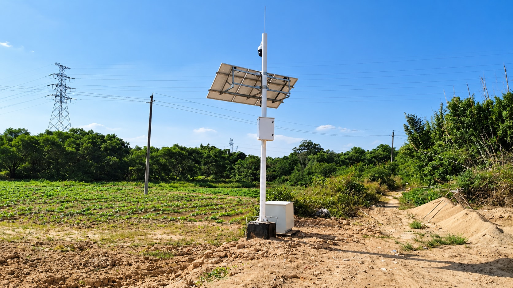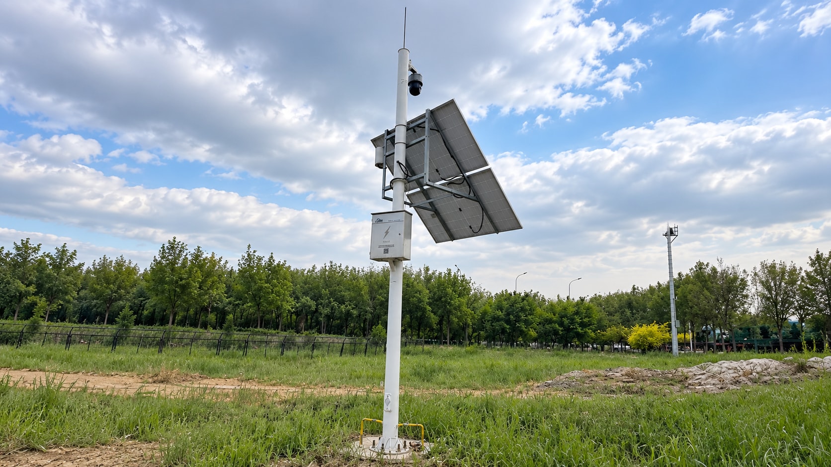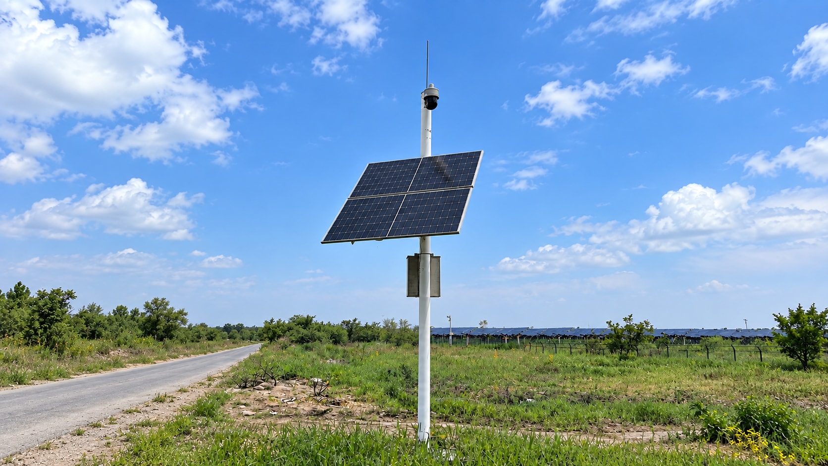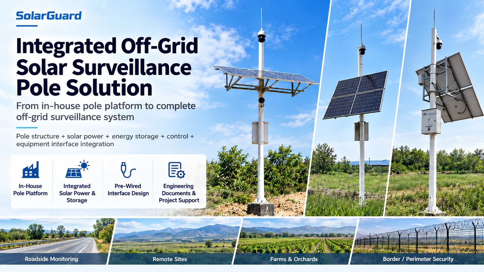
From an in-house pole platform to a complete off-grid surveillance system
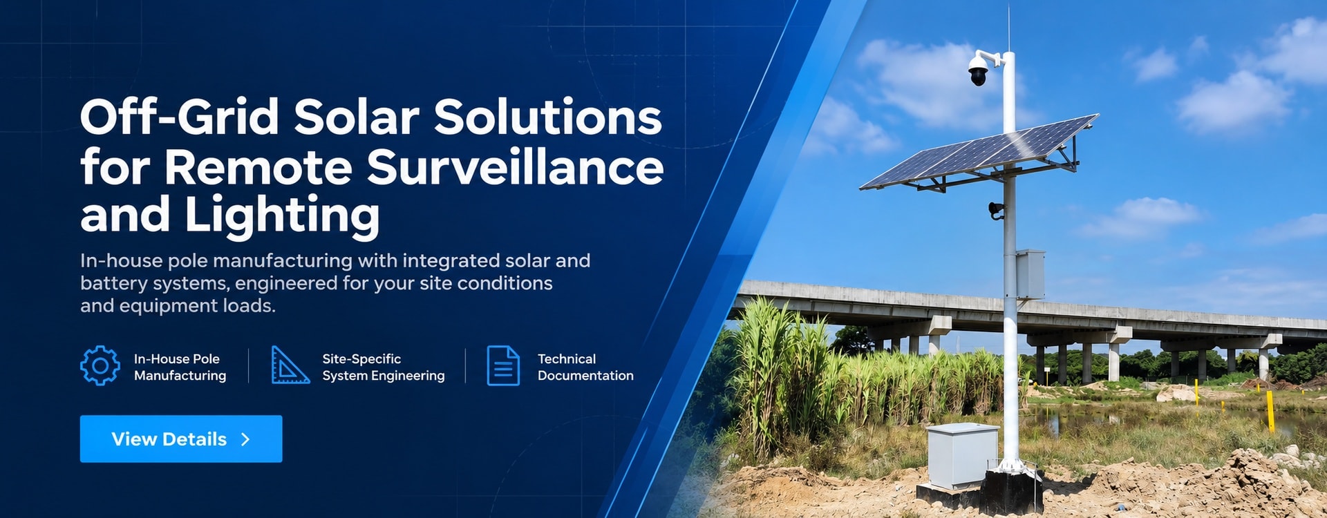
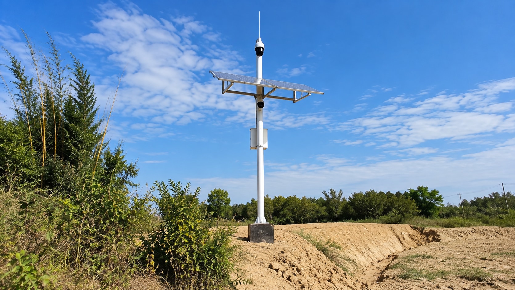
For sites without reliable grid power, where trenching is difficult or rapid deployment is required, we offer two delivery options: a pole-only configuration or a fully integrated off-grid surveillance system. The pole is engineered and manufactured in-house, while solar generation, energy storage, control, power distribution, and equipment interfaces are matched to actual project conditions.
Core positioning: Electrical equipment is not added to a finished pole as an afterthought. Structural design, electrical configuration, and equipment interfaces are coordinated from the project configuration stage.
IN-HOUSE POLE MANUFACTURING | ELECTRICAL SYSTEM INTEGRATION | UNIFIED INTERFACES | PROJECT-BASED DELIVERY | ENGINEERING SUBMITTALS | SINGLE POINT OF RESPONSIBILITY
Why a Pole + Electrical System Should Not Be Treated as a Simple Assembly
The challenge in an off-grid surveillance project is not simply mounting a solar module, battery, and camera on a pole. The real issue is whether the structure, power system, equipment interfaces, and project documentation work together as one system.
When these parts are designed separately, common project risks include:
→Added solar modules increase projected wind area and shift the system center of gravity.
→Cameras, radar units, battery enclosures, and other payloads may be excluded from the complete structural check.
→Brackets, cable routes, and interfaces may require modification only after equipment reaches the site.
→Responsibility can become unclear across pole, electrical, and equipment suppliers.
→Technical documents come from multiple sources, making project review and site execution more difficult.
→Any initial savings from split procurement can be quickly offset by rework, coordination, and schedule delays.
Our approach: move as many interface risks as possible from the jobsite to the project configuration and factory stage.
One Pole Platform, Two Procurement Options
The same solar surveillance pole platform can be supplied in different ways depending on the customer’s existing supply chain and project capability.
| Option A — Pole-Only Configuration | Option B — Complete Off-Grid Surveillance System |
| Best for customers that already have their own solar, battery, controller, or surveillance equipment supply chain. | Best for projects that want to reduce multi-vendor coordination and on-site integration work. |
We provide: • Pole structure • Solar module mounting structure • Camera/equipment mounting points • Battery/control enclosure interfaces • Internal cable routing provision • Flange and foundation interface • Corrosion protection system • Custom mechanical interfaces | Integrated on the same pole platform: • Solar modules • Energy storage system • Charge controller • Power distribution and protection • Battery/control enclosures • Communication equipment interfaces • Camera and other payload interfaces • Pre-wiring and pre-assembly • Engineering drawings and project documentation |
| The customer completes the electrical configuration, equipment selection, and system integration. | The pole platform is upgraded from a mechanical support structure to a complete off-grid surveillance system. |
Bottom line: one platform, two delivery models. The pole-only option covers the mechanical support function; the integrated solution addresses system integration risk.
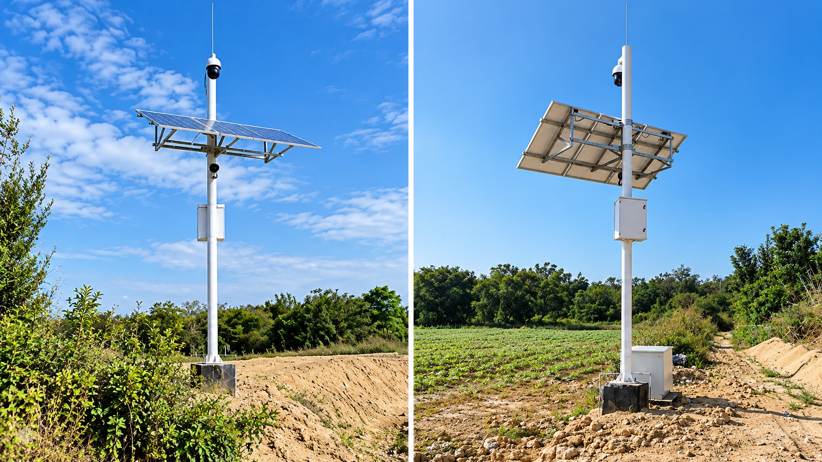
We Integrate More Than Components
Integration is not about adding more components. It is about engineering them to work together from the start.
◆ Structural Integration
Solar module size and position, cameras/radar/lighting, battery enclosure weight, mounting height, projected wind area, eccentric loads, flange, anchor bolts, and foundation conditions are considered together during design.
Result: the structural check is based on the fully equipped pole system, not the bare pole alone.
◆ Electrical Integration
Solar modules, batteries, controllers, power distribution/protection, and device power interfaces are matched to actual load, operating hours, solar resource, required autonomy, ambient temperature, and load type.
Result: the objective is not simply more panel wattage or battery capacity, but a power system that fits the load, pole and site conditions.
◆ Interface & Delivery Integration
Solar interfaces, camera mounting points, enclosure bases, internal cable routes, cable entries, grounding path, service access, and terminal/interface labels are completed or reserved before shipment.
Result: fewer on-site holes, welds, cable rerouting, and temporary modifications.
Why In-House Pole Manufacturing Matters to System Integration
The advantage isn't that we manufacture every component in-house. The key is that we control the primary mechanical load-bearing platform through our own engineering and manufacturing.
When solar modules, battery enclosures, cameras, or communication equipment change, we can adjust:
◎Pole section and wall thickness
◎Bracket configuration
◎Equipment mounting positions
◎Enclosure location
◎Cable routing space
◎Service access openings
◎Flange and foundation configuration
As a result, the electrical system does not have to be forced onto a fully fixed standard pole, and the pole does not have to be modified on site to accommodate electrical equipment.
Responsibility boundary: pole structure, corrosion protection, and installation interfaces are produced by our own factory. Solar modules, energy storage, controllers, and power distribution use qualified external components, but all are incorporated into the overall design and verification process.
What the Integrator Actually Gains
| Split Procurement | Integrated Delivery |
| Coordinate pole, electrical, and equipment suppliers separately | Single project interface |
| Repeated structural/equipment confirmation | Unified verification based on the complete configuration |
| Electrical system must adapt to an existing pole | Pole and electrical system are matched together |
| On-site drilling, welding, and cable rerouting | Maximum practical pre-assembly and interface reservation |
| Technical documents collected from multiple suppliers | Coordinated project documentation |
| Complex responsibility boundaries when issues occur | Clearer technical responsibility |
Core value: not more equipment, but less uncertainty during project execution.
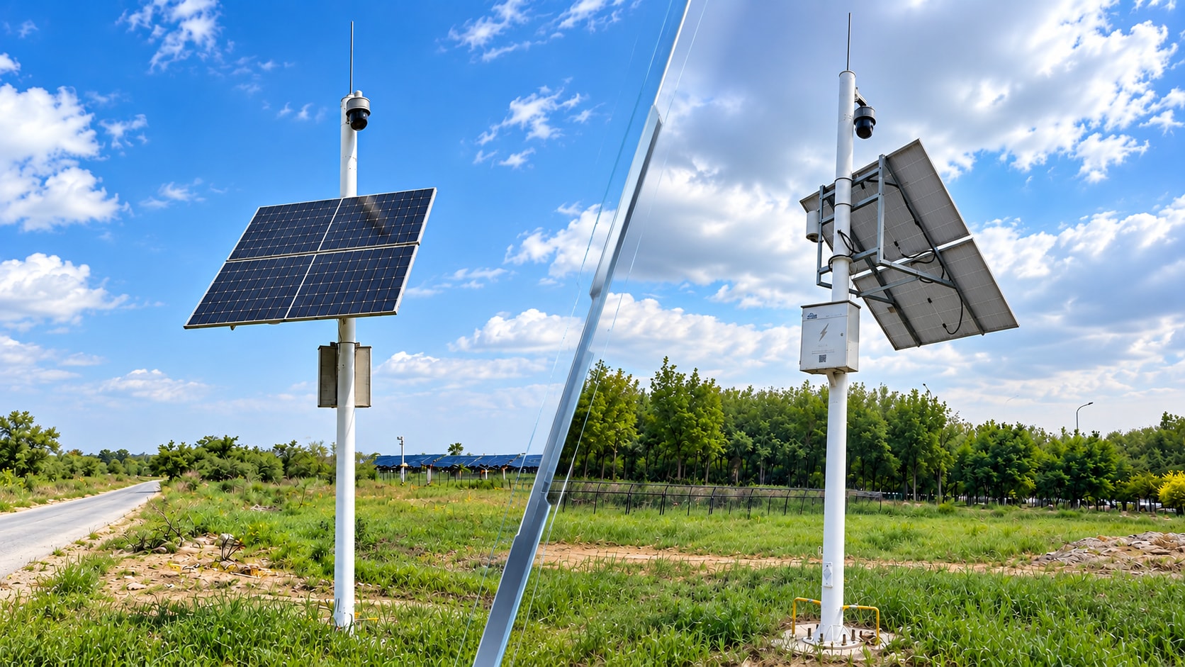
Where This Integrated Model Makes the Most Sense
| Project Type/Typical Challenge | Integrated Value |
Oil & gas/border / remote sites | Independent power, fewer site visits |
Mining/ports High wind, corrosion, heavy payloads | Coordinated structural and corrosion design |
Wildfire monitoring Remote locations, low temperatures, multiple devices | Low-temperature energy storage and multi-device integration |
Coastal/river environments Salt spray, humidity, corrosion | Coordinated corrosion protection and outdoor interfaces |
Farms/orchards High trenching cost, distributed sites | Rapid deployment and independent power |
Project-specific environmental adaptation may include:
→High- or low-temperature configuration
→Corrosion protection for coastal and high-humidity environments
→Sand and dust protection
→Structural reinforcement for high-wind regions
→Low-temperature energy storage
→Outdoor enclosure and interface protection
Design principle: do not claim one configuration fits every environment. Identify the site risk and address it in the pole, electrical system and equipment configuration.
Maintenance and Configuration Choices
▲Fixed: For standard projects. Simple structure and lower initial cost.
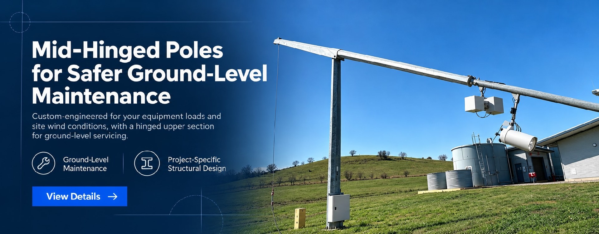
▲Base-Hinged: Reduces work-at-height frequency and allows equipment to be serviced closer to ground level.
▲Lowering System: For projects that meet structural and payload limits.
Engineering note: The maintenance method must be coordinated with equipment weight, pole structure, cable routing, and foundation design. Lowering systems are recommended only for light-load applications below 8 m; automatic lowering is not recommended for 10–12 m heavy-duty poles.
| Typical Configuration Levels | |
| Configuration | Typical Positioning/Applications |
| Standard | Conventional off-grid surveillance Industrial parks, farms, temporary worksites |
| Enhanced | Longer autonomy, multiple devices Roads, mines, ports, border sites |
| Heavy-Duty | Higher loads, more devices, harsh environments Coastal sites, high-salinity environments, extreme climates |
Final project configuration is matched to actual load, solar resource, wind conditions, and mounted equipment. Project-specific structural verification is required; reference configurations should not be copied directly into final design.
Project Documentation and Engineering Support
Integrated delivery is not only about shipping the equipment together. The engineering documents are also developed around the same project configuration rather than assembled from unrelated supplier documents.
→Structural & Civil
◎Pole structural drawings
◎Equipment layout drawings
◎Foundation drawings
◎Structural calculation data
◎Wind-load related documentation
◎Electrical wiring diagrams
→Electrical & Corrosion
◎Electrical configuration description
◎Corrosion protection specification
→Installation & Compliance
◎Installation and maintenance documents
◎Major component certification documents
◎Multilingual installation manuals
◎Technical videos
Small-batch trial orders of 5–10 poles are supported. Project-specific engineering support can be provided for applicable standards such as EN 1090 and AS/NZS 1170, subject to the actual project scope and available certification.
From Pole-Only Supply to a Complete Off-Grid Surveillance System
If you already have your own electrical system, the solar surveillance pole can be purchased separately. If you want to reduce coordination between structural, electrical, and on-site installation work, the same pole platform can be supplied with integrated solar generation, energy storage, control, power distribution, and equipment interfaces.
Bottom line: one pole platform, two delivery models. Pole-only supply covers the mechanical support function; the integrated solution reduces system integration risk.
Information Required for Initial Configuration
◎Project country/region
◎Application
◎Pole height
◎Cameras and other mounted equipment
◎Equipment power consumption
◎Required autonomy during consecutive low-sun / overcast days
◎Design wind speed
◎Environmental conditions
◎Preferred maintenance method
◎Remote O&M requirement