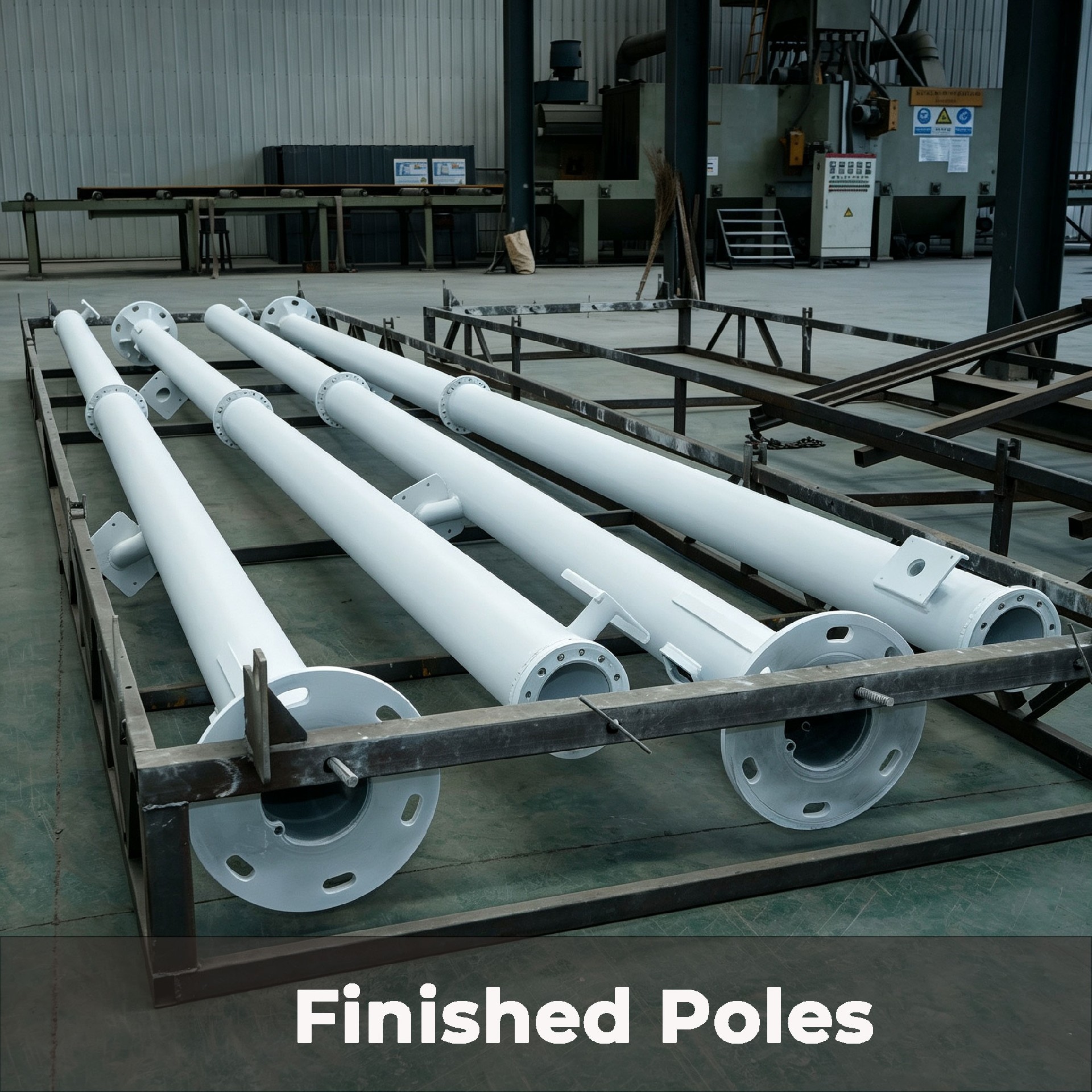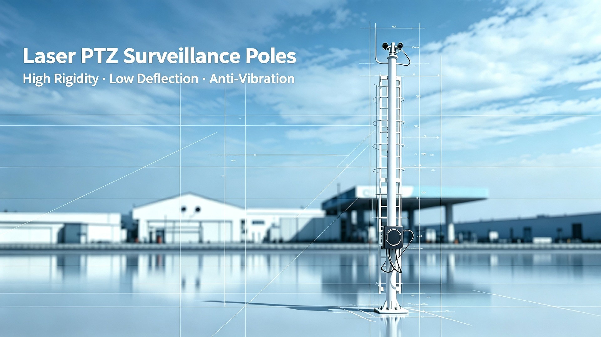
Our Laser PTZ Surveillance Poles are high-rigidity structural masts engineered for long-range laser PTZ, thermal imaging, and multi-sensor perimeter security. Optimized for micro-vibration suppression and tight deflection control down to L/300, they prevent optical-axis drift common with conventional low-rigidity camera poles.
Supplied in high-strength carbon steel or SS316L stainless steel, these factory-prefabricated poles support payloads from 150 kg to 300+ kg and design wind speeds up to 50 m/s, suited for industrial, coastal, border, and port harsh-environment surveillance deployments.
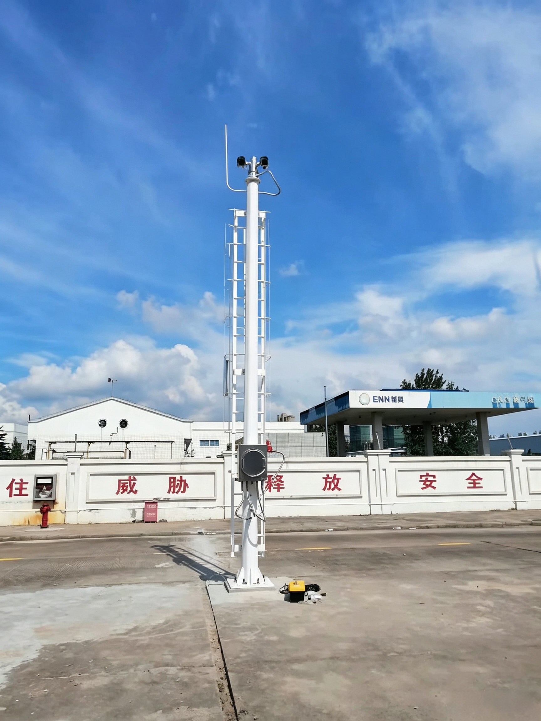
High-rigidity structural pole with prefabricated mounting platform, ladder, junction box, and foundation interface — engineered specifically for long-range laser PTZ payloads. (Camera, laser illuminator, and control system integration handled by your end-user/EPC.)
1. High-Stiffness Structure for Laser Optical-Axis Stability
Engineered exclusively for long-range laser surveillance systems to control structural deflection and suppress wind-induced micro-vibrations. Eliminates far-field image blurring and target offset caused by pole swaying. Stiffness standards can be calibrated to project-specific deflection limits such as L/300 or higher precision requirements.
2. Custom Heavy Payload Capacity for Multi-Sensor Integration
Designed to support combined installations of full-size long-range laser PTZ cameras, thermal imagers, perimeter radars, and auxiliary IoT monitoring devices. All structural load calculations reserve adequate safety margins based on actual equipment weight and wind load conditions, preventing permanent deformation and fatigue under continuous operation.
3. Factory Prefabrication for Optical-Grade Installation
Reinforced top mounting platforms, heavy-load brackets, and large-diameter internal cable conduits are entirely pre-processed in the factory. Strict machining flatness control ensures optimal laser mounting accuracy. No on-site cutting, drilling, or welding is required, preserving coating integrity and preventing optical calibration drift caused by field modifications.
For laser PTZ deployments where structural stability directly impacts optical accuracy, we provide the following engineering validation documents to support your project technical approval and bidding submission:
📐 Deflection Calculation Report — Maximum tip deflection under design wind load + rated payload combination, full-section deflection curve.
📊 Modal Analysis Report — Natural frequency analysis to confirm separation from the vortex-shedding resonance range.
🔬 Dynamic Response Analysis — Structural response under wind-induced vibration and PTZ rotation dynamic torque.
📋 FEA Report — Full 3D finite element stress distribution and safety factor verification.
These reports are available upon request for EPC projects and high-standard port deployments.
| Parameter | Specification |
| Effective Hight | 4–15m, fully customizable according to project site |
| Rated Total Payload | Up to 300 kg |
| Applicable Equipment | Long-range laser PTZ camera, thermal imaging PTZ, perimeter radar, multi-sensor composite monitoring equipment |
| Structural Stiffness & Deflection | up to H/300 |
| Material | Q355B Carbon Steel or SS316L Stainless Steel (material selected per project environment) |
| Surface Finish | Hot-dip galvanized + powder coating (Carbon Steel) / brushed + passivated (Stainless Steel) |
| Dynamic Performance | Finite element dynamic analysis, vortex-induced resonance avoidance design |
| Notes: Dimensions, payload, and corrosion performance are project‑specific, subject to site wind‑load calculation. All specifications are for reference only. | |
| Material | Surface Treatment | Applicable Scenarios |
| Q355B CS | Sa2.5 surface preparation + hot-dip galvanizing + multi-layer powder coating duplex system | Inland industrial parks, urban perimeter, mild coastal areas |
| SS316L | Brushed & passivated full anti-salt-spray treatment | Port terminals, wharves, offshore adjacent areas, strong salt spray industrial zones |
Global Standards Adaptation & Compliance Delivery
Supported by an ISO 9001:2015 quality management system, we can adapt pole design, manufacturing quality control, corrosion protection, and technical documentation to project-specific standards and local requirements, supporting overseas project approval, procurement, and acceptance.
Structural Design & Wind Load Verification: Structural calculations can be performed in accordance with EN 40 / EN 1993, AASHTO, applicable AS/NZS standards, SASO requirements, or other project-specified codes. Design verification can incorporate site wind speed, equipment loads, mounting height, and environmental conditions.
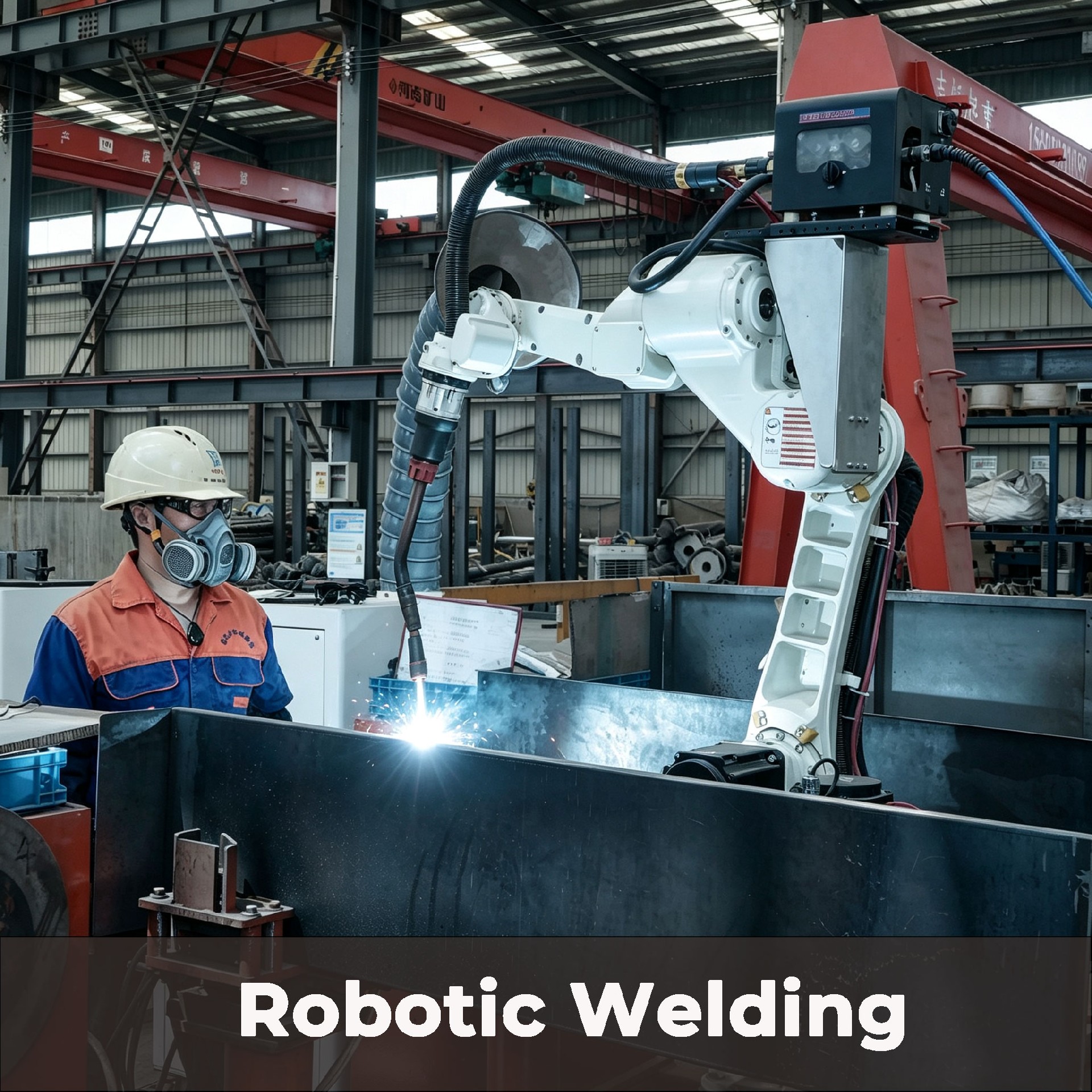
Welding & Manufacturing Control: Welding procedures and quality control can be adapted to applicable EN 1090 execution requirements and ISO 3834 welding quality requirements, with corresponding process, inspection, and documentation controls implemented as required by the project.
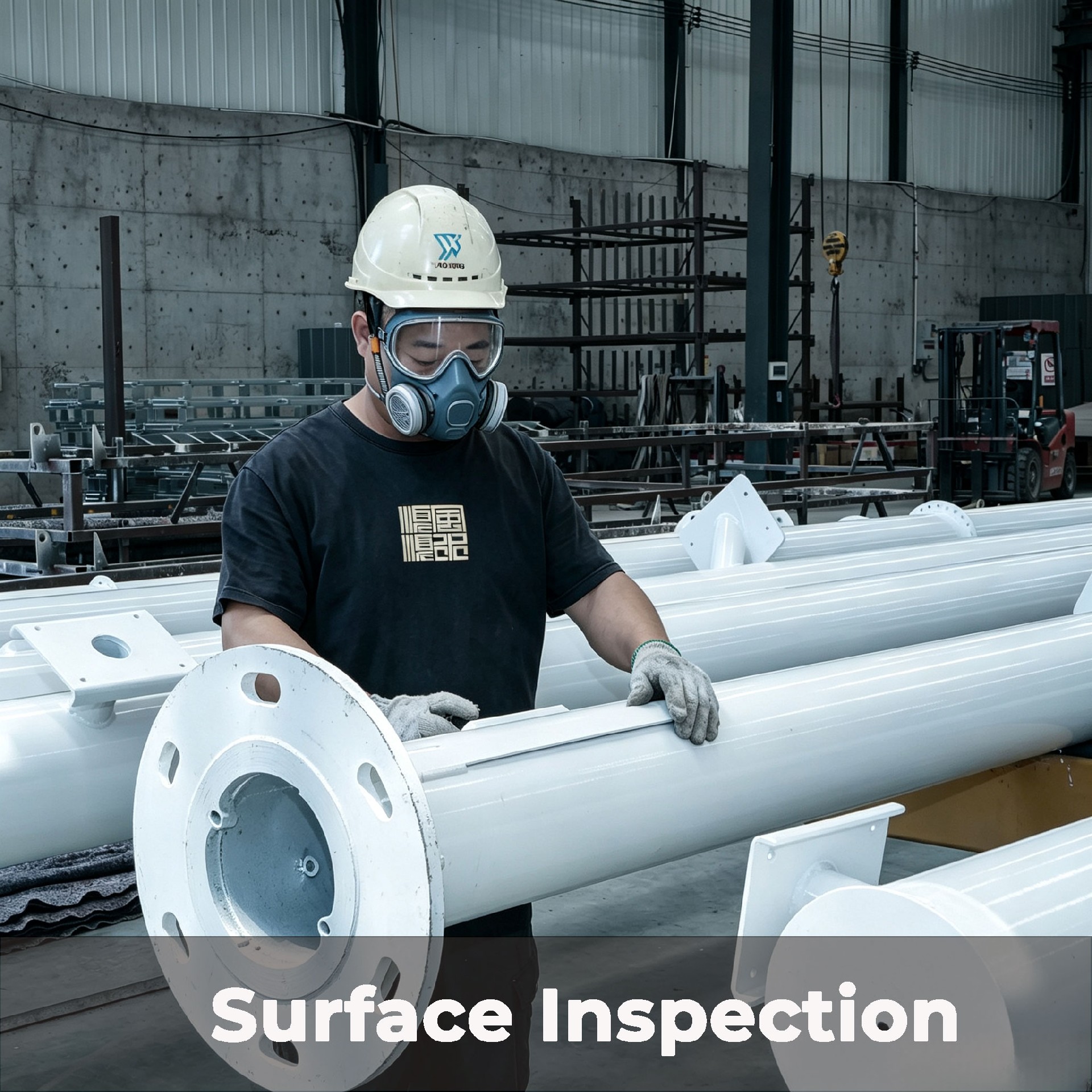
Corrosion Protection: Hot-dip galvanizing and coating systems can be configured according to the project environment and required service life. Treatments can be specified to ISO 1461, ASTM A123/A123M, or other project requirements for standard outdoor, coastal, high-humidity, and high-salinity environments.
Engineering Documentation Support: Project documentation can include structural calculation reports, shop drawings, material certificates, welding records, galvanizing or coating inspection reports, dimensional inspection records, and factory quality documentation for client, consultant, or EPC review.
Multi-Market Project Support: We support project requirements across Europe, North America, the Middle East, and Asia-Pacific. Applicable design standards, inspection requirements, and document packages can be defined according to the project location and technical specification.
Standard camera poles feature low rigidity and lack vibration suppression. Under gusty winds, micro-deflection and high-frequency resonance occur. For long-range laser PTZs, tiny structural shakes amplify into severe optical-axis offset, leading to blurred monitoring, lost target tracking, and frequent manual recalibration. This laser-dedicated pole adopts thick-walled, tapered high-strength sections and reinforced flange welding technology. Dynamic finite element analysis (FEA) verifies the first-order natural frequency to avoid vortex-induced vibration resonance intervals, while structural stiffness meets rigorous standards like L/300.Delivers an ultra-stable mounting datum that maintains long-term laser aiming accuracy, drastically reduces on-site debugging and maintenance workloads, and ensures continuous, reliable operation of perimeter security systems.
Ordinary poles are designed for lightweight equipment and lack the load margin required for heavy laser PTZs and multi-device stacked installations. Overload leads to local stress concentration, structural tilt, and fatigue damage, impairing optical stability. Structural parameters—including wall thickness, section size, and reinforcement—are custom-designed based on project equipment configurations, actual payload weights, and local wind profiles. Top reinforced mounting platforms evenly disperse concentrated loads, and structural verification accounts for dynamic torque generated by high-speed PTZ rotation. Stably supports the integrated operation of laser, thermal, radar, and environmental sensors without deformation or offset, providing robust mechanical support for multi-dimensional surveillance systems.
Integrators often struggle with mismatched anti-corrosion specs: over-engineered marine coatings inflate costs for inland projects, while insufficient treatments cause premature coating failure in coastal salt-spray environments. We offer two standardized, application-matched solutions. The carbon steel version utilizes Sa 2.5 high-standard surface preparation, duplex hot-dip galvanizing, and a multi-layer paint system for C4 inland industrial and mild coastal settings. The SS316L stainless steel version achieves full ISO 12944 C5-M marine-grade performance against heavy salt spray and high humidity. Precisely matches site conditions to achieve an optimal balance between long service life and project cost.
Precision optical devices demand extreme mounting flatness and stability. Traditional on-site secondary processing (like drilling and welding) damages protective coatings, creating hidden corrosion points while introducing flatness errors that cause optical-axis tilt and inaccurate positioning. The factory precisely prefabricates and positions all functional elements—including heavy-load bases, specialized laser brackets, and internal wiring channels. Top flange mounting flatness is strictly controlled within tight project tolerances, allowing assembly without destructive site modifications. Protects coating integrity, guarantees optical installation accuracy, standardizes construction procedures, and shortens project delivery cycles.
|
|
|
|
|
|
Broad Compatibility with Major Security Equipment
Industrial-grade precision mounting interfaces and reinforced brackets enable seamless integration with mainstream professional security devices from leading global brands.
Cameras: Long‑range laser PTZ, infrared thermal imagers, high‑speed dome PTZ — compatible with light, medium, and heavy‑duty PTZ units across all major payload classes.
Sensors: Perimeter surveillance radars, environmental monitoring sensors, traffic detection sensors, and methane gas detection.
Auxiliary Equipment: Outdoor security power cabinets, industrial control units, and custom protective enclosures.
🔧 Precision‑Grade Mounting Adaptation: Flange hole patterns, platform dimensions, and bracket layouts are fully customizable to customer‑supplied CAD drawings. Top‑mount brackets are manufactured using high‑precision laser cutting to ensure an exact fit with camera and PTZ bases from Axis, Hanwha, Bosch, and other major brands. Bracket geometry accounts for eccentric dynamic loads induced by PTZ rotation. On‑site drilling is eliminated, ensuring error‑free installation and meeting the integration demands of multi‑sensor laser surveillance systems.
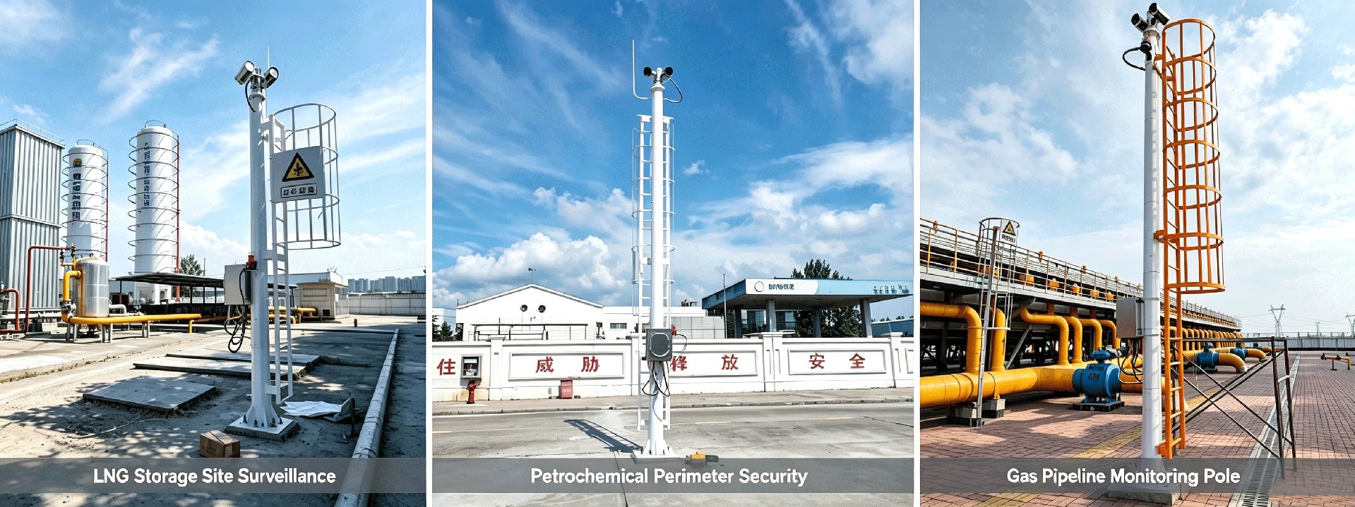
Proven Project Deployments
LNG Storage Site Surveillance: 10m Heavy‑Duty Poles, 28 Units, delivering reliable anti‑corrosion performance for hazardous‑area operation.
Petrochemical Perimeter Security: 9m Ladder‑Integrated Heavy‑Duty Poles, 42 Units, supporting multi‑sensor mounting for long‑term perimeter protection.
Gas Pipeline Monitoring: 8m Heavy‑Load Poles, 36 Units, providing high wind‑resistance for continuous outdoor surveillance.
⚡ Galvanic Corrosion Prevention: Install dielectric isolating gaskets at all dissimilar-metal joints, including segmented flange interfaces and top flange connections with aluminum PTZ housings. This is mandatory for coastal and high-humidity environments to prevent galvanic corrosion that compromises long-term structural integrity and imaging stability.
💧 Drainage & Sealing: Ensure base drainage weep holes remain unobstructed and handhole covers are securely sealed. Never embed base flange plates underground or backfill soil over them. Maintain clean and unobstructed internal conduits to facilitate continuous cable routing and heat dissipation.
🛡️ Surface & Flange Protection: Protect hot-dip galvanized/powder-coated carbon steel or passivated stainless steel surfaces from mechanical damage during handling and installation. Pay special attention to the precision-machined top mounting flange; any deformation or scratches will compromise flatness and laser optical alignment. Promptly apply compatible touch-up paint to any compromised areas.
🔌 Grounding & Lightning Protection: Ensure proper grounding and equipotential bonding in compliance with local electrical codes. Maintain continuous electrical conductivity across all pole sections to guarantee effective lightning protection and stable operation of sensitive laser PTZ and radar systems.
🏗️ Foundation & Verticality Control (Critical for PTZ): Anchor bolts and concrete foundations must meet local wind-load requirements and project-specific reaction data. Do not erect poles until the concrete has reached its full design strength. Strictly control base flange levelness and overall verticality during installation; structural tilt directly causes laser offset, image drift, and tracking failure in long-range observation systems.
We provide custom wind-load calculation reports, 2D CAD drawings, installation manuals, and tender technical documents to support your global project approvals and customs clearance.
For general-purpose technical handbooks and safety guidelines, please visit our Download Center→
🚀 Rapid Delivery: Typically ship within 3–5 weeks.
💰 Volume Pricing: Tiered pricing structures available for bulk orders.
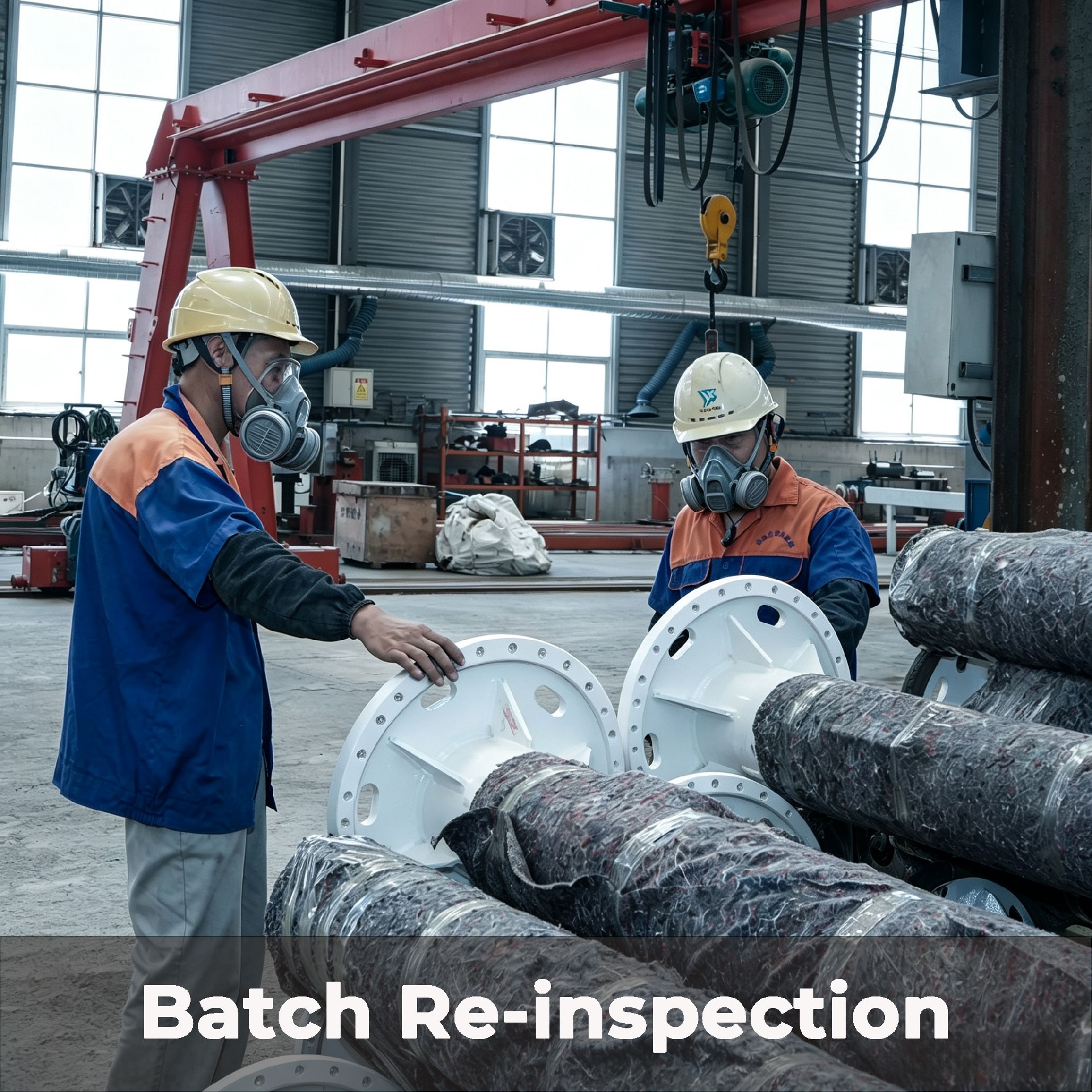
📦 Export-Grade Packaging: Moisture-proof and shock-resistant packaging optimized for safe container loading.
📊 Real-Time Tracking: Dedicated project managers providing regular production progress updates.
Q1: How do you ensure the pole won’t resonate with wind‑induced vortex shedding?
Each pole design undergoes modal analysis to verify that the first-order natural frequency remains distinct from the vortex shedding frequency across the entire operating wind speed range. Vortex shedding frequency is calculated using the Strouhal relationship: f = St × V / D. The pole’s tapered geometry, wall thickness profile, and overall height are iteratively optimized to prevent frequency coincidence at any wind speed below the design limit. For projects in high-turbulence environments (e.g., coastal areas, open terrain), we can integrate tuned mass dampers or helical strakes upon request. Modal analysis reports are available for project review upon request.
Q2: Can the pole handle the dynamic torque generated by high-speed PTZ slewing?
Yes. Our structural design fully accounts for the dynamic eccentric torque generated during high-speed PTZ rotation (up to 100°/s horizontal, 60°/s vertical). Both torsional rigidity and foundation moment capacity are verified under combined static and dynamic loading conditions. Additionally, most heavy-duty PTZ heads with worm-gear drive mechanisms provide inherent self-locking performance, effectively suppressing oscillatory feedback transmitted to the pole structure.
Q3: Will H/300 stiffness guarantee zero image shake for laser PTZ?
No — and it is important to manage this expectation clearly. Our H/300 stiffness standard ensures pole-tip displacement stays within the tracking-compensation capability of most professional-grade PTZ drives under design wind loads. However, absolute "zero shake" cannot be guaranteed by pole stiffness alone. Imaging stability is a system-level outcome influenced by multiple factors:
①Site Wind Turbulence: Local terrain, nearby structures, and thermal updrafts can create gust patterns exceeding uniform design wind speeds.
②PTZ Tracking Algorithm: The responsiveness and bandwidth of the PTZ's closed-loop stabilization system directly affect residual image motion.
③Foundation Stiffness: A soft or poorly compacted foundation can amplify low-frequency sway beyond calculated H/300 values.
④Installation Quality: Improper bolt torque, misaligned flanges, or uneven base grouting can introduce structural asymmetry.
For projects requiring maximum imaging stability, we recommend combining H/300 pole stiffness with PTZ units featuring electronic image stabilization (EIS) and/or mechanical gyro-stabilized platforms.
Q4: Are the top flange dimensions standard or custom-made for PTZ devices?
Our top-mount flanges are available in two configurations to match specific integration requirements:
①Flat Plate Flange: Fully custom-drilled according to your PTZ unit drawing. We verify bolt circle diameter, bolt quantity, hole size, and anti-rotation keyway dimensions against your equipment CAD data. Flatness tolerance is guaranteed at ≤0.5 mm, ensuring direct bolt-on installation with zero field rework.
②Slip Flange: Features a through-hole bolt design to accommodate minor on-site alignment adjustments, offering greater installation tolerance for projects where equipment selection may change during integration.
Both configurations are precision-machined post-welding to eliminate thermal distortion, and all bolt holes are CNC-drilled to a positional tolerance of ±0.5 mm.
Q5: Can you provide base-flange loading data for civil foundation design?
Yes. We supply a comprehensive foundation design data package, including:
①Reaction Loads: Base overturning moment, horizontal shear force, and axial compression corresponding to your selected pole height, rated payload, and design wind speed.
②Base Flange Drawing: Bolt layout, bolt circle diameter, and anchor bolt positions.
③Anchor Bolt Specifications: Recommended grade (e.g., Grade 8.8 / 10.9), diameter, embedment depth, and edge distance.
④Base Plate Thickness: Specified per design load case.
All data is derived from the same structural calculation model used for the pole design, ensuring full consistency between superstructure loads and foundation input parameters.
Q6: Can you accommodate custom equipment layouts for my specific PTZ model?
Yes. We customize all bracket positions, conduit entries, and access openings based on your PTZ equipment CAD drawings. Our engineering team verifies device dimensions, cable routing, and cooling requirements to deliver a fully plug-and-play pole system.
Q7: Can I send my own third-party inspector to your factory?
Absolutely. We fully support third-party inspections by SGS, BV, TÜV, Lloyd’s Register, or any client-nominated agency. Standard inspection hold points include material verification, pre-weld fitting, post-weld NDT, coating inspection, and final dimensional checks before shipment.
Q8: How is the pole segmented for shipping?
Poles exceeding 12 m are divided into 2–3 sections connected by internal high-strength flanges. This segmented design complies with standard 40HQ container dimensions and typical on-site crane capacities while maintaining full structural rigidity after assembly. Flange joints are engineered to transfer 100% of bending moments and shear forces.
Specifications are typical values for reference only under standard conditions — not a guarantee. Final performance shall be determined by project design calculations and factory test reports. Consult a local engineer before specifying.
| Customization available | MOQ: 1 |
| Lead Time | 3‑5 weeks upon drawing approval and receipt of deposit |
| Payment | 30% T/T deposit; 70% balance before shipment. L/C at sight is acceptable. |
| Inspection | Third‑party factory inspections available (SGS / BV / TÜV) |