Transforming Elevated Maintenance into Ground-Level Operations
In perimeter security, mining sites, ports, highway corridors, energy storage facilities, and water conservancy monitoring, critical edge devices—such as PTZ cameras, illuminators, and radars—must be deployed at elevated heights. However, sites often lack safe, cost-effective conditions for working at height. Elevated work platforms (EWPs/cherry pickers) struggle with site access; traffic control and road closures incur high operational costs, and working at height involves strict liability risks, steep insurance premiums, and mandatory permits. As the density and distribution of pole locations scale up, lifecycle HSE management and Operation & Maintenance (O&M) costs compound continuously.
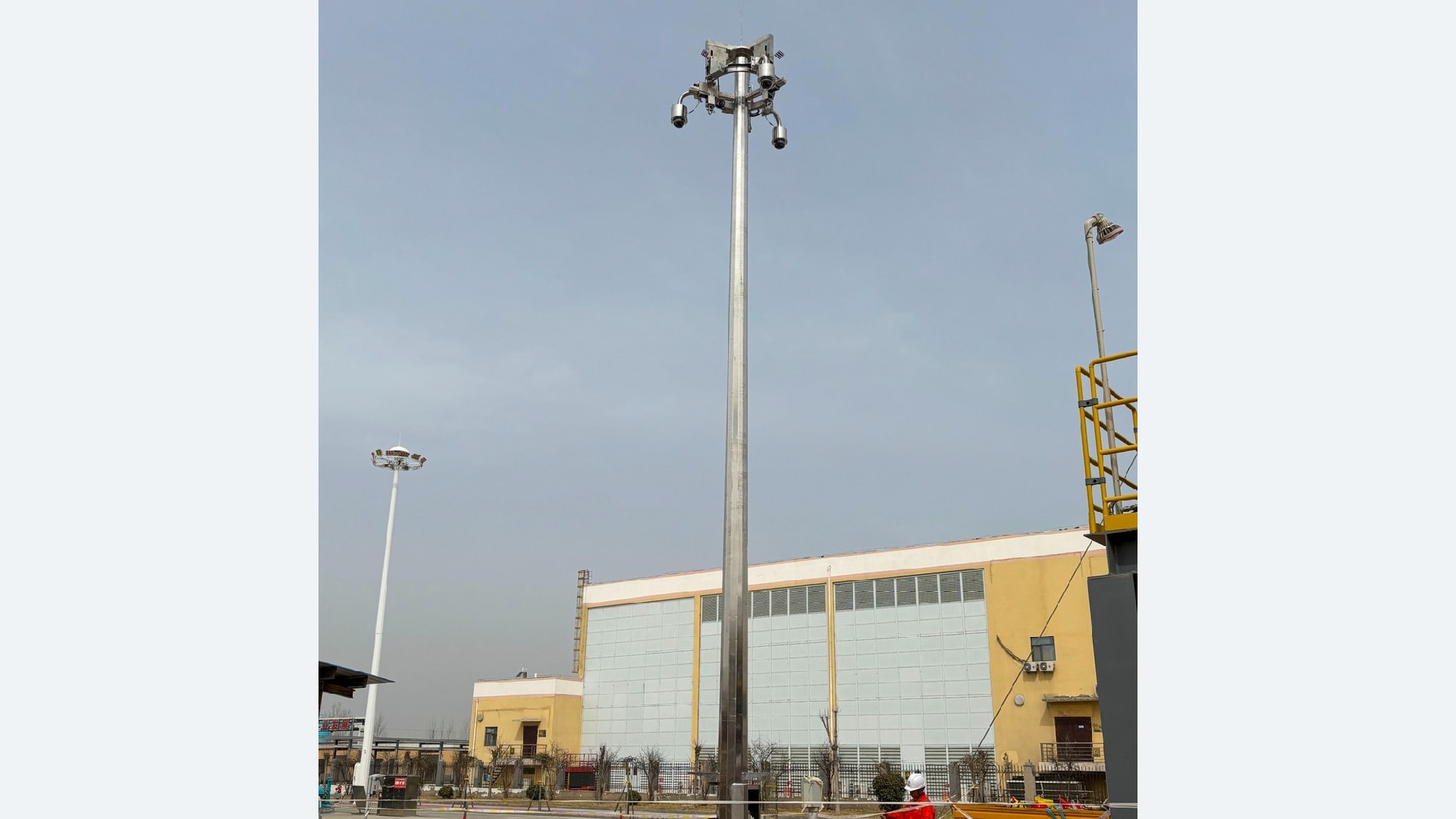
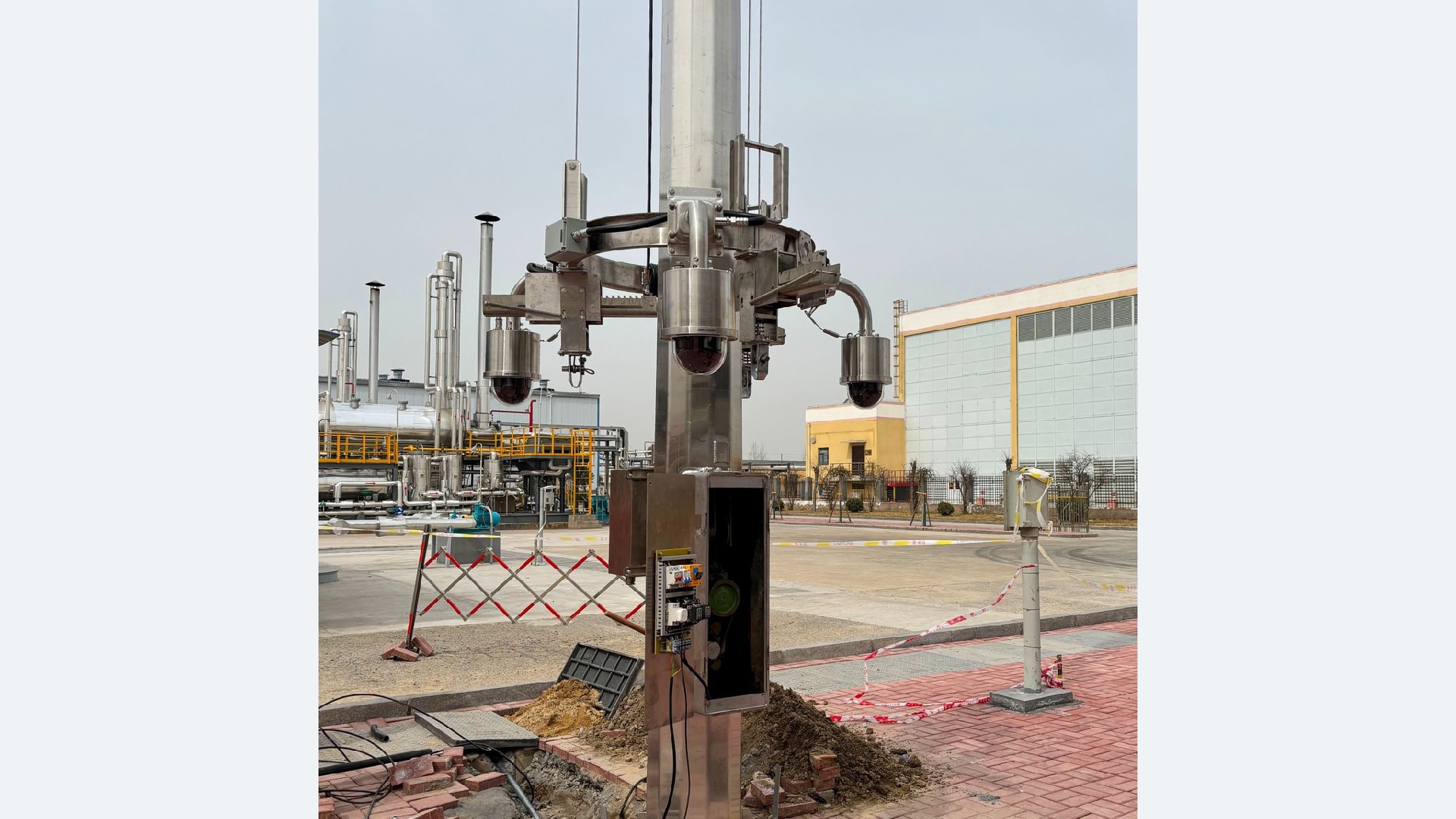
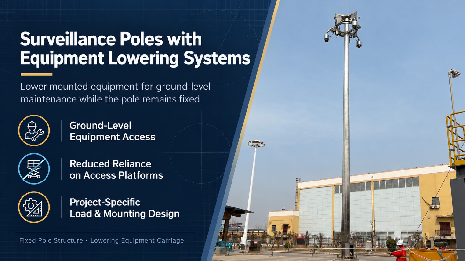
The Lowerable Surveillance Mast remains completely vertical during operation, with only the top equipment platform moving vertically. During servicing, equipment is lowered directly to ground level, eliminating both working at height and the need to tilt the entire mast structure.
Fixed Masts: Equipment remains permanently elevated. Every routine maintenance check requires working at height, driving up operational costs and triggering burdensome approval workflows.
Tilt-Down Masts: Tilting requires a large lateral clearance radius. In space-constrained sites or dense layout zones, adjacent poles interfere with one another, severely limiting site adaptability.
Lowerable Masts: Eliminate the lateral drop radius. Perfectly suited for space-constrained sites, dense pole layouts, congested underground utilities, and high-traffic corridors.
→Objective Limitations: Capital expenditure (CAPEX) is higher than traditional fixed masts. Because the lifting winch mechanism is a mechanical moving assembly, wire ropes, motors, and cable management systems require scheduled maintenance to ensure long-term operational stability.
Professional engineering procurement teams look beyond basic "lifting functionality," focusing heavily on long-term structural reliability and compliance:
■ Are the lifting mechanism and structural stability reliable under high wind loads and dynamic vibrations?
■ Do cables suffer from stretching, abrasion, or water ingress after repeated raising and lowering cycles?
■ Is there a risk of uncontrolled drop during a power outage?
■ Does the corrosion protection system meet long-term service life requirements in coastal, desert, or extreme cold environments?
■ Can complete, archive-ready, and verifiable structural engineering documentation be provided for project permit approvals?
→Lifting Mechanism
Engineered with clearly specified safe working load (SWL), lateral force limits, lifting speeds, wind-lock anti-fall protection, back-drive prevention, emergency manual descent, ingress protection (IP) rating, operating temperature range, lifting cycle lifespan, and manual override functions. Tailored adaptation assessments are conducted for special environmental conditions such as coastal high humidity, extreme thermal cycling, high winds, and equipment vibration.
→Cable Protection System
Engineered for vertical reciprocating motion, utilizing specialized internal routing paths that eliminate the flaws of conventional fixed-pole wiring. This effectively minimizes cable tension, bending stress, and wear risks while providing independent, layered protection for power lines, signal lines, and grounding systems.
→Structural Integrity
We deliver comprehensive structural calculations including equipment dead load schedules, wind load combinations, overturning moment curves, anchor reaction forces, mast-top deflection data, and foundation reference drawings to satisfy project consultant and engineer review requirements.
→Corrosion Protection System
Selected in accordance with ISO 12944 corrosivity categories. Carbon steel shafts feature a duplex corrosion protection system consisting of hot-dip galvanizing (HDG) plus outdoor-grade electrostatic powder coating. Stainless steel masts utilize SS304 or SS316L with surface passivation. Full test reports covering zinc layer thickness, coating adhesion, salt spray resistance, and weathering performance are available. Compliant with C3/C4/C5-M multi-level environmental specifications. For high-corrosion environments such as coastal zones, ports, and de-icing salt spray zones, downsizing material grades and anti-corrosion specifications is strictly prohibited.
Each lowerable surveillance mast is supplied with a comprehensive, permit-ready document package:
◎ General Assembly Drawings & Installation Load Schedule
◎ Wind Load Calculation Report
◎ Overturning Moment Curves
◎ Anchor Bolt Reaction Data & Foundation Reference Drawings
◎ Bolt Tightening Standard Procedure Sheet
◎ Material Quality Certificates
◎ Galvanization & Coating Test Reports
◎ Lifting Mechanism Factory Acceptance Test (FAT) Records
Standard Configuration Lead Time: 21–28 days
Customized Configuration Lead Time: 28–35 days (calculated from drawing sign-off and deposit receipt)
1. Client Input: Project location, governing standards, design wind speed, equipment schedule.
2. Joint Confirmation: Equipment dead weight, effective projected area (EPA), mounting height, power supply, and cabling requirements.
3. Supplier Engineering: Matching lifting mechanism specifications, corrosion protection grade, and junction box configuration.
4. Final Sign-Off: General assembly drawings, structural calculation reports, foundation reference drawings.
5. Execution: Manufacturing, factory inspection, protective crating, and logistics delivery.
6. After-Sales Support: Installation manual, video guidance, and full lifecycle traceability documentation.
Note: Preliminary load assessments can be provided early based on basic project data. When preliminary data is incomplete, we supply standard reference parameter ranges; we issue complete technical packages ready for tender and official permit submission once full specifications are confirmed.
Jump to : Commercial Terms | FAQ | Delivery Commitment
| Item | Parameter |
| Pole Height | 6m – 12m (standard range; heights above 12 m require project-specific wind-load and structural verification) |
| Material | Carbon steel(Q235B/Q355B) / Stainless Steel(304/316L) |
| Lifting Platform Load | Static load: 50 kg (standard) / 100 kg (custom) Dynamic factor: lifting impact and safety margin already considered |
| Lifting Travel | 2m - 6m |
| Lifting Speed | 0.08 – 0.15 m/s (factory preset) |
| Drive Mechanism | Electric winch + mechanical self-locking + anti-backlash device |
| Drive Unit IP Rating | IP65 (standard) / IP66 (optional for high dust or coastal sites) |
| Operating Temperature | -20 °C to +50 °C (standard) |
Supported by an ISO 9001:2015 quality management system, we can adapt pole design, manufacturing quality control, corrosion protection, and technical documentation to project-specific standards and local requirements, supporting overseas project approval, procurement, and acceptance.
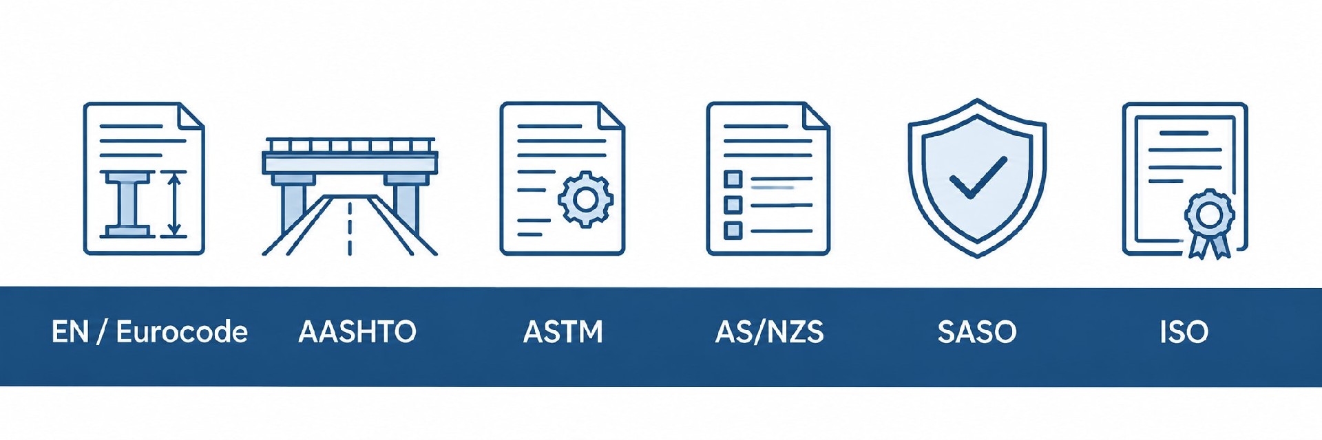
Structural Design & Wind Load Verification: Structural calculations can be performed in accordance with EN 40 / EN 1993, AASHTO, applicable AS/NZS standards, SASO requirements, or other project-specified codes. Design verification can incorporate site wind speed, equipment loads, mounting height, and environmental conditions.
Welding & Manufacturing Control: Welding procedures and quality control can be adapted to applicable EN 1090 execution requirements and ISO 3834 welding quality requirements, with corresponding process, inspection, and documentation controls implemented as required by the project.
Corrosion Protection: Hot-dip galvanizing and coating systems can be configured according to the project environment and required service life. Treatments can be specified to ISO 1461, ASTM A123/A123M, or other project requirements for standard outdoor, coastal, high-humidity, and high-salinity environments.
Engineering Documentation Support: Project documentation can include structural calculation reports, shop drawings, material certificates, welding records, galvanizing or coating inspection reports, dimensional inspection records, and factory quality documentation for client, consultant, or EPC review.
Multi-Market Project Support: We support project requirements across Europe, North America, the Middle East, and Asia-Pacific. Applicable design standards, inspection requirements, and document packages can be defined according to the project location and technical specification.
Term | Detail |
| Customization | Supported — MOQ 1 unit |
| Lead time | Standard configuration: 3–4 weeks / Custom-engineered configuration: 4–5 weeks |
| Payment terms | 30% T/T advance · 70% before shipment · L/C at sight accepted |
| Trade terms | EXW: Specify named place FOB: Specify port of shipment CFR / CIF: Specify destination port |
| Inspection support | Third-party factory inspection by SGS / BV / TÜV welcomed |
| Samples | Available — sample cost credited against first production order |
⚡ Galvanic Corrosion Prevention: Carefully match fastener materials. When connecting dissimilar metals, use isolating non-conductive gaskets. (Service option: Pre-installed nylon/EPDM isolation gaskets available upon request).
💧 Drainage & Sealing: Keep base drainage openings unobstructed; hand-hole covers and seals must remain intact. Never bury flange plates underground.
🛡️ Surface Protection: Protect coated, passivated, and brushed surfaces from mechanical scratches during installation. Repair damaged areas with material-matched touch-up treatment: touch-up coating for carbon steel/aluminium coated finishes, local passivation for stainless steel.
🔌 Grounding Requirement: Complete proper grounding and equipotential bonding in compliance with local electrical codes.
🏗️ Foundation Rules: Anchor bolts and concrete foundations must satisfy local wind-load requirements. Erect poles only after concrete has fully cured.
We provide custom wind-load calculation reports, 2D CAD drawings, installation manuals, and tender technical documents to support your global project approvals and customs clearance.
For general-purpose technical handbooks and safety guidelines, please visit our Download Center→
🚀 Rapid Delivery: Standard orders ship in 3–5 weeks. Custom schedules available.
🔒 Secure Financing: Staged payments via T/T or L/C ensure financial control.
👤 Dedicated Management: A dedicated project manager provides real-time production updates.
📦 Reliable Packaging: Moisture-proof and shock-resistant packaging ensures safe container and ocean transit.
📄 Technical Documentation: Full engineering files, including structural calculations, ship with every order.
Selection & Application
Q1: What are the target application scenarios?
A: Suitable for scenarios involving elevated equipment deployment, high-altitude maintenance challenges, and high O&M costs, such as border security, mining sites, logistics yards, ports, expressway perimeters, energy storage stations, perimeter security for airports, and water conservancy monitoring.
Q2: Is it possible to mount multiple devices simultaneously on the same platform, such as a PTZ camera, radar, and supplemental light?
A: Yes, integrated multi-device deployment is supported. You need only provide the total equipment weight, combined windage area, and mounting hole requirements; our engineering team will incorporate the total payload into the comprehensive structural calculation.
Q3: Can the lifting speed be customized? Can it be adjusted on-site?
A: The lifting speed can be preset before delivery according to project requirements. Once factory-set and locked, parameters cannot be adjusted on-site.
Structural Reliability & Environmental Adaptability
Q4: What is the maximum allowable lateral load for the lifting platform?
A: Lateral force limits are determined through specialized structural calculations based on project design wind speed and pole height, with exact values specified in the structural calculation report. The platform design reserves load margins to resist wind-induced vibration and impact loads.
Q5: Will the cables suffer from wear and tear?
A: The system utilizes specialized reciprocating cable routing designed for lifting equipment—differing from standard fixed-pole wiring. Power, signal, and grounding systems feature multi-layered protection to prevent cable wear, abrasion, and tension-related failures.
Q6: Does the platform automatically lock in the event of a power outage? Is there a manual descent function?
A: The mechanism is equipped with an integrated power-off anti-drop locking device, which immediately secures the platform upon power loss. A standard manual emergency release mechanism is included, allowing equipment to be lowered to the ground for maintenance without an external power supply.
Q7: Is personnel boarding permitted on the lifting platform?
A: The platform is strictly designated for carrying monitoring, lighting, and other sensing equipment. Personnel boarding is strictly prohibited, and the structural design load does not account for human weight.
Q8: Are specialized evaluations required for extreme cold or high-vibration scenarios (such as near roads or railways)?
A: Yes. Low-temperature environments require frost-resistant lubrication and cold-adapted lifting mechanisms. Continuous vibration accelerates fatigue in moving parts; therefore, site conditions must be disclosed in advance for specialized structural verification.
Q9: What is the standard Ingress Protection (IP) rating for the lifting drive mechanism?
A: The standard protection rating for the drive mechanism is IP65, with upgradeable protection configurations available for coastal, high-salinity, dusty, or high-humidity environments.
Specifications are typical values for reference only under standard conditions — not a guarantee. Final performance shall be determined by project design calculations and factory test reports. Consult a local engineer before specifying.