Product Overview
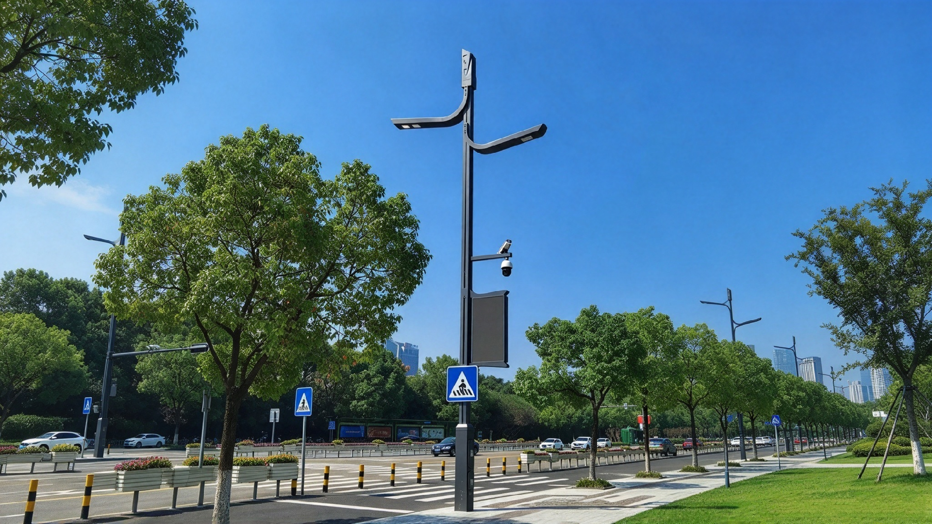
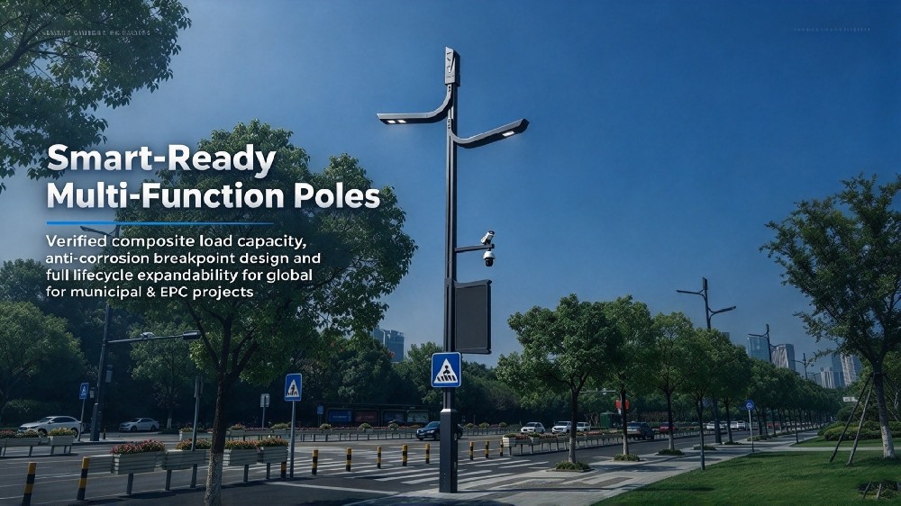
Smart street light poles serve as shared outdoor infrastructure carriers for mounting lighting, surveillance, communication, environmental monitoring, and information display hardware. Unlike conventional light poles, they address five specific engineering challenges: composite load, cabinet thermal management, equipotential bonding, localised corrosion risks, and future equipment expansion.
Scope of Supply: Pole shaft, mounting platforms, luminaire brackets, control cabinet housing, cable duct, flange and anchor bolts
Not Supplied: Luminaires, cameras, 5G small cells, sensors, display screens and other electrical hardware
Responsibility Boundary
- Us: Pole structural safety, mounting system, corrosion protection, earthing continuity, cabinet structure and full structural calculation documentation
- Client / Equipment Vendor: Equipment selection, power supply, communication, software and electrical integration & commissioning
Disclaimer: We provide anchor load data and reference foundation drawings. Final civil foundation design must be completed by a locally licensed civil engineer with a geotechnical report.
Luminaire arms, camera clamps, small-cell antennas, environmental cabinets, and digital signage sit at different heights, with different eccentricities and wind-exposed areas. Applying a single-luminaire calculation gives only two outcomes: over-design that inflates foundation cost, or an original design load exceeded as soon as a second device is added.
■ Mounting load schedule — mass, mounting height, eccentricity, and wind area listed per device; flat-plate components such as digital signage are verified as a separate wind load case
■ Multi-load-case wind verification report — combined per the code specified for the project, with overturning moment curve and anchor bolt reactions (twin-pole / flanged base options)
■ Spare load capacity — ≥30% additional capacity reserved at manufacture (verified to remain satisfied against the final mounted configuration), with the permissible additional equipment mass and mounting height range confirmed in writing
■ Addition without pole replacement — within the reserved capacity, we re-verify the loads and supply compatible brackets; neither the pole nor the foundation requires replacement. Beyond the reserved capacity, the design is re-checked, and the client is notified in writing in advance
Avoids third-party re-check fees and rejection by the engineer of record or owner; prevents the common rework of "no capacity left after the first device".
Minimum 30% spare load capacity reserved; permissible additional mass and mounting height range confirmed in writing.
The enclosure concentrates power, surge protection, control, and communications modules. Solar gain on the sun-facing side and day–night condensation are the two leading causes of module failure.
■ Placement — mounted on the shaded side, with solar shield and insulation pad; bottom-in / top-out natural convection; forced cooling optional above 150 W internal dissipation
■ Measured temperature rise ≤15 K (ambient 40 °C / irradiance 1000 W/m² / no wind / steady state, natural convection). Test report shipped with the goods; third-party witnessed retest supported
■ Ingress and condensation — IP55 standard / IP65 optional (IP65 recommended for coastal, dusty and de-icing-salt routes); pressure-equalising structure, optional heated dehumidifier for cold-climate and coastal projects
■ HV/LV separation — physical partition or clearance ≥100 mm; provision for surge arrester and earth bar; access door oriented away from the dominant sun direction and operable from ground level with standard tools
The figure is a temperature rise above ambient (K), not an absolute internal temperature; equipment operating temperature is to be derived by the equipment supplier from local ambient conditions.
Measured temperature rise ≤15 K above ambient (40 °C / 1000 W/m² / no wind / steady state).
A multi-device pole means multiple HV/LV circuits sharing one grounding path. Corroded or interrupted bonding points cause intermittent equipment faults in years 3–5 that are extremely difficult to trace on site — a failure mode that does not exist on a conventional street light pole.
■ Continuous equipotential bonding of the shaft and every mounting point, using flexible jumpers (≥16 mm² copper braid) so that repeated removal and bending cannot break the path
■ Galvanic isolation at dissimilar-metal contacts (e.g. carbon-steel pole against aluminium device brackets), while electrical continuity is maintained
■ Bonding points listed as a 12-month inspection item, delivered with the installation manual
■ Overall grounding system design, earth electrodes, and earth resistance values remain the client's electrical scope under the applicable local code (≤10 Ω is a common requirement; NESC-based jurisdictions differ). We provide the bonding and terminal provisions
The weak points are not on the shaft — they are the mounting holes, bracket welds, clamp contact faces, enclosure door gaps, flange mating faces, and bonding points, all introduced by multi-device mounting.
■ Holes, bevels and drilled bores treated to the same grade and recorded individually; welds and cut edges treated to parent-metal grade, with thickness records
■ Door gaps, drainage channels, hinges, flange mating faces and anchor threads sealed or edge-sealed
■ Carbon steel — hot-dip galvanising to ISO 1461 / ASTM A123, graded by plate thickness: ≥6 mm ≥85 µm / 3–6 mm ≥70 µm / 1.5–3 mm ≥55 µm / <1.5 mm ≥45 µm, measured per piece including bore interiors; optional duplex system to ISO 12944 C4/C5-M with 60–120 µm coating and adhesion test
■ Stainless steel/aluminium — not suitable for hot-dip galvanising; passivation or coating (316L recommended for coastal), or anodising/fluorocarbon coating respectively; isolation at dissimilar-metal contacts
■ C4 or higher recommended for coastal and de-icing-salt routes — we flag downgrade risk rather than accept it silently. Minor on-site damage repaired per ASTM A780; one touch-up can (≥400 ml) supplied per set
Equipment will be replaced and upgraded within the design life. If the mounting structure is not adaptable, every change requires field drilling — and every drilled hole is a coating breach and a future corrosion point.
■ Factory-prefabricated mounting interfaces: slide rails, adjustable clamps or standard flanges, compatible with mainstream device hole centres (commonly 70×70, 100×100, 150×150 mm, prefabricated per the client's equipment schedule)
■ Mounting height adjustable on a 100 mm module along the shaft, azimuth adjustable 0–360°, with scale markings and locking bolts
■ Hole positions and angles prefabricated at the factory from the approved equipment schedule — no field welding, no field drilling
■ Digital signage brackets verified separately as flat-plate wind loads; clearance between the display's lower edge and the shaft ≥100 mm (100–200 mm recommended for heat dissipation and self-shading), with shading-angle reference provided
■ Mounting bolts with anti-theft heads plus anti-loosening washers
Field-weld-free and field-drilling-free assembly; interfaces pre-fabricated per approved equipment schedule.
Jump to : Commercial Terms | FAQ | Delivery Commitment
| Item | Parameter |
| Pole Height | 3–12 m, per load verification (6–12 m typical for smart poles) |
| Material | Carbon steel(Q235B/Q355B) / Stainless Steel(304/316L)/ Aluminum Alloy(6063‑T6/ 6061‑T6)(Customizable) |
| Shaft | Monopole tapered / round (polygon optional); wall thickness 3–8 mm |
| Mounting system | Slide rails / adjustable clamps/flanges, compatible with mainstream device hole centres (prefabricated per equipment schedule) |
| Spare load capacity | ≥30%; permissible additional mass and mounting height range confirmed in writing |
| Enclosure | IP55 standard / IP65 optional; measured temperature rise ≤15 K; surge arrester position and earth bar provided |
| Cable duct | Continuous, HV/LV separated (partition or clearance ≥100 mm), with access door |
| Equipotential bonding | Continuous bonding of shaft and all mounting points, flexible jumpers ≥16 mm², listed as a 12-month inspection item |
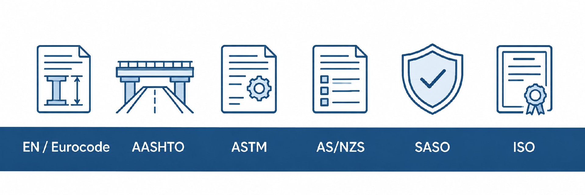
Supported by an ISO 9001:2015 quality management system, we can adapt pole design, manufacturing quality control, corrosion protection, and technical documentation to project-specific standards and local requirements, supporting overseas project approval, procurement, and acceptance.
Structural Design & Wind Load Verification: Structural calculations can be performed in accordance with EN 40 / EN 1993, AASHTO, applicable AS/NZS standards, SASO requirements, or other project-specified codes. Design verification can incorporate site wind speed, equipment loads, mounting height, and environmental conditions.
Welding & Manufacturing Control: Welding procedures and quality control can be adapted to applicable EN 1090 execution requirements and ISO 3834 welding quality requirements, with corresponding process, inspection, and documentation controls implemented as required by the project.
Corrosion Protection: Hot-dip galvanizing and coating systems can be configured according to the project environment and required service life. Treatments can be specified to ISO 1461, ASTM A123/A123M, or other project requirements for standard outdoor, coastal, high-humidity, and high-salinity environments.
Engineering Documentation Support: Project documentation can include structural calculation reports, shop drawings, material certificates, welding records, galvanizing or coating inspection reports, dimensional inspection records, and factory quality documentation for client, consultant, or EPC review.
Multi-Market Project Support: We support project requirements across Europe, North America, the Middle East, and Asia-Pacific. Applicable design standards, inspection requirements, and document packages can be defined according to the project location and technical specification.
Term | Detail |
| Customization | Supported — MOQ 1 unit |
| Lead time | Standard configuration: 3–4 weeks / Custom-engineered configuration: 4–5 weeks |
| Payment terms | 30% T/T advance · 70% before shipment · L/C at sight accepted |
| Trade terms | EXW: Specify named place FOB: Specify port of shipment CFR / CIF: Specify destination port |
| Inspection support | Third-party factory inspection by SGS / BV / TÜV welcomed |
| Samples | Available — sample cost credited against first production order |
⚡ Galvanic Corrosion Prevention: Carefully match fastener materials. When connecting dissimilar metals, use isolating non-conductive gaskets. (Service option: Pre-installed nylon/EPDM isolation gaskets available upon request).
💧 Drainage & Sealing: Keep base drainage openings unobstructed; hand-hole covers and seals must remain intact. Never bury flange plates underground.
🛡️ Surface Protection: Protect coated, passivated, and brushed surfaces from mechanical scratches during installation. Repair damaged areas with material-matched touch-up treatment: touch-up coating for carbon steel/aluminium coated finishes, local passivation for stainless steel.
🔌 Grounding Requirement: Complete proper grounding and equipotential bonding in compliance with local electrical codes.
🏗️ Foundation Rules: Anchor bolts and concrete foundations must satisfy local wind-load requirements. Erect poles only after concrete has fully cured.
We also provide custom wind-load calculation reports, 2D CAD drawings, installation manuals, and tender technical documents to support your global project approvals and customs clearance.
For general-purpose technical handbooks and safety guidelines, please visit our Download Center→
🚀 Rapid Delivery: Standard orders ship in 3–5 weeks. Custom schedules available.
🔒 Secure Financing: Staged payments via T/T or L/C ensure financial control.
👤 Dedicated Management: A dedicated project manager provides real-time production updates.
📦 Reliable Packaging: Moisture-proof and shock-resistant packaging ensures safe container and ocean transit.
📄 Technical Documentation: Full engineering files, including structural calculations, ship with every order.
Scope & responsibility
Q1. Do you supply luminaires, cameras, small cells, sensors or displays?
A: By default, no — we supply the structural system only (shaft, mounting platform, arms, enclosure, cable duct, flange and anchor bolts). Equipment bodies are selected by you or your supplier. Integrated supply can be agreed separately with separate responsibilities and quotations.
Q2. Can an existing street light pole be upgraded to carry additional devices?
A: Yes, subject to verification. We require as-built or measured data (height, wall thickness, base details) plus the new device list. If the existing pole is insufficient, we propose reinforcement, a replacement segment, or a new pole, with the load re-check documented.
Structure & codes
Q3. Do you consider seismic and ice/snow loading?
Where the governing local code requires it, seismic action and ice accretion on the shaft and mounted devices are included in the load combination. This must be stated at the inquiry stage — it affects wall thickness, base design, and anchor bolt selection, and cannot be added after fabrication.
Q4. What about antennas and small cells — wind-induced vibration and fatigue?
Slender and lattice-type attachments are assessed for wind-induced vibration, dynamic amplification, and fatigue, and preferred mounting positions are recommended in the calculation report.
Q5. Are serviceability limits such as top deflection checked?
Yes. Deflection and rotation at the top are checked against the limits of the governing code and reported in the calculation package, together with the governing load case.
Specifications are typical values for reference only under standard conditions — not a guarantee. Final performance shall be determined by project design calculations and factory test reports. Consult a local engineer before specifying.