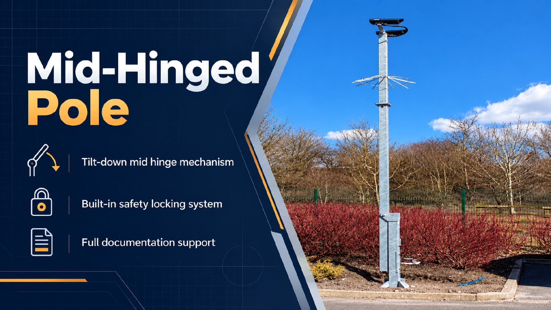
Product Overview
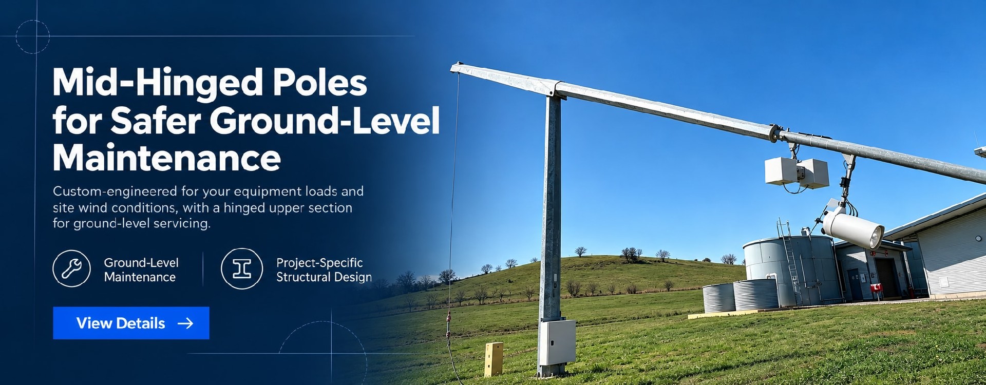
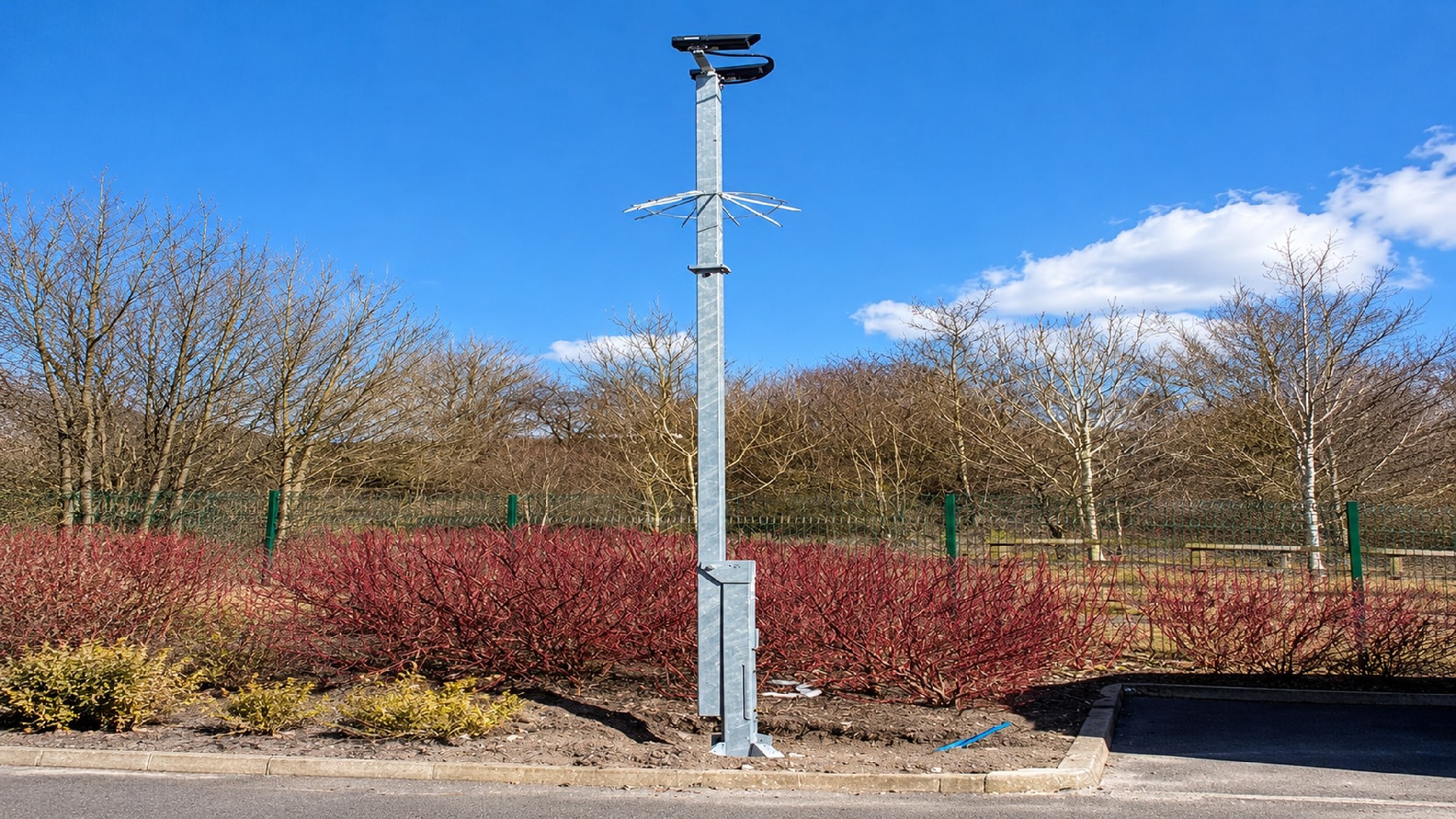
Mid-hinged CCTV poles are engineered for remote security infrastructure—including mine perimeters, oilfield boundaries, border surveillance, highway networks, and waterway monitoring. These sites often impose heavy eccentric loads from multi-sensor PTZ cameras and millimeter-wave radar, where mobile elevated work platforms (MEWPs) are impractical, and tight perimeter footprints leave minimal clearance for conventional pole-lowering arcs.
Traditional fixed poles require costly elevated work for installation and maintenance, driving up labor expenses and safety liability. Meanwhile, full-length tilt-down poles demand an extensive swing radius, leading to clearance conflicts in high-density deployments. Mid-hinged CCTV poles eliminate both challenges: the lower section remains fixed upright while only the upper segment tilts in a controlled arc. This enables ground-level installation, calibration, and servicing of all mounted equipment within severely restricted site constraints.
The primary engineering advantage is simple: all top-mounted devices can be installed, commissioned, inspected, and replaced safely at ground level, eliminating working at height.
Project Benefits: Eliminates the need for cranes, bucket trucks, or certified rope-access technicians.
Cost Efficiency: Drastically reduces field installation man-hours and long-term Operations & Maintenance (O&M) expenditures.
Space Optimization: Safe lowering dynamics prevent pole-to-infrastructure collisions in dense perimeter layouts.
Engineering & Structural Highlights
1. Dual-Stage Mechanical Safety Locking
Available with a self-locking worm-and-wormgear mechanism(optional) that resists back-driving forces from high wind loads and eccentric weights, preventing accidental pole drop. An independent mechanical safety pin provides secondary positive locking, mitigating human error during maintenance and ensuring strict compliance with international workplace safety standards (including OSHA requirements).
2. Heavy-Duty Structural Integrity
The hinge assembly, connecting flanges, stiffening ribs, and wall thickness are structurally reinforced to handle heavy eccentric loads from high-payload PTZ cameras and radar units. The rigid design minimizes deflection under extreme wind conditions, preserving stable video streams and consistent radar tracking performance. Structural load capacity exceeds standard mid-hinged lighting poles.
3. Integrated Cabling & Multi-Device Mounting
Internal, dedicated sealed cable raceways, weatherproof junction boxes, and standard grounding points are pre-fabricated within the shaft. This accommodates multi-device and multi-cable routing without requiring on-site drilling. Mounting heights, bracket geometries, and junction box layouts can be customized to match specific project engineering drawings.
4. All-Weather Corrosion Resistance
Carbon steel poles feature a duplex corrosion protection system: hot-dip galvanizing (HDG) followed by an exterior-grade architectural powder coat.
For high-risk applications — high-wind regions, marine environments, and critical infrastructure — supplementary FEA, wind-load simulation, and fatigue testing are available upon request. Every unit undergoes full-cycle lowering, locking, and reset functional testing before factory dispatch.
Complete engineering documentation packages are available upon request, including structural calculation reports, weld inspection certificates (NDT), corrosion test records, and Factory Acceptance Test (FAT) reports. Custom engineering modifications—such as bespoke equipment brackets, non-standard mounting heights, and alternative junction box configurations—are fully supported per project specifications.
Jump to : Commercial Terms | FAQ | Delivery Commitment
| Item | Parameter |
| Pole Height | 4 m – 12 m (customizable per project) |
| Material | Carbon steel(Q235B/Q355B) |
| Wall Thickness | 4–10 mm (nominal; min. wall ≥ 95% of nominal, per material standard; customized per project) |
| Manufacturing tolerances | Flange flatness: base flange ≤ 0.5 mm; mid-section locking flange ≤ 0.2 mm, shaft straightness ≤L/750, bolt hole deviation ±1.5mm |
| Pole Joint | Base flange to foundation; mid-hinge assembly with locking flange for upper-section lowering |
| Max Top Mount Payload | 80-200 kg(including brackets; rated load accounts for wind load factor per EN 40; value varies with pole height and hinge location) |
| Compatible Additional Equipment | Heavy‑duty PTZ cameras, perimeter radar, environmental sensors, site lighting fixtures (optional) |
| Surface Treatment | Hot-dip galvanizing (≥85μm) + outdoor electrostatic powder coating |
| Junction Box IP Rating | IP65/IP66 (optional) |
Supported by an ISO 9001:2015 quality management system, we can adapt pole design, manufacturing quality control, corrosion protection, and technical documentation to project-specific standards and local requirements, supporting overseas project approval, procurement, and acceptance.
Structural Design & Wind Load Verification: Structural calculations can be performed in accordance with EN 40 / EN 1993, AASHTO, applicable AS/NZS standards, SASO requirements, or other project-specified codes. Design verification can incorporate site wind speed, equipment loads, mounting height, and environmental conditions.
Welding & Manufacturing Control: Welding procedures and quality control can be adapted to applicable EN 1090 execution requirements and ISO 3834 welding quality requirements, with corresponding process, inspection, and documentation controls implemented as required by the project.
Corrosion Protection: Hot-dip galvanizing and coating systems can be configured according to the project environment and required service life. Treatments can be specified to ISO 1461, ASTM A123/A123M, or other project requirements for standard outdoor, coastal, high-humidity, and high-salinity environments.
Engineering Documentation Support: Project documentation can include structural calculation reports, shop drawings, material certificates, welding records, galvanizing or coating inspection reports, dimensional inspection records, and factory quality documentation for client, consultant, or EPC review.
Multi-Market Project Support: We support project requirements across Europe, North America, the Middle East, and Asia-Pacific. Applicable design standards, inspection requirements, and document packages can be defined according to the project location and technical specification.
Our poles feature pre-drilled Mounting interfaces and universal brackets, ensuring seamless integration with mainstream global brands:
Cameras: Bullet, PTZ, Dome (Standard Interface), Laser PTZ.
Sensors: Environmental, Traffic & Methane Gas Detection.
Enclosures: Universal Security Power Supplies & Battery Enclosures.
🔧 Precision Fit: Custom hole drilling, crossarms, and flange patterns are available upon request based on CAD templates. Precision laser-cut top brackets can be tailored to specific camera footprints (e.g., Axis, Hanwha, Bosch), eliminating on-site drilling and accelerating installation.
Mine & Open‑pit Perimeter Security
- Recommended Height: 8–12 m
- Corrosion Grade: C3/C4
- Notes: Heavy‑payload radar & multi‑sensor PTZ; dusty operating environment
Oilfield / Refinery Perimeter
- Recommended Height: 8–12 m
- Corrosion Grade: C4/C5‑M
- Notes: Coastal or industrial chemical atmosphere; dense‑spacing deployment
Border & Remote Frontier Surveillance
- Recommended Height: 6–10 m
- Corrosion Grade: C3/C4
- Notes: No MEWP access; limited swing clearance for lowering
Highway & Road Network Monitoring
- Recommended Height: 6–9 m
- Corrosion Grade: C3
- Notes: Road‑side installation, compact lowering radius
Water Conservancy / Reservoir Monitoring
- Recommended Height: 8–10 m
- Corrosion Grade: C4/C5‑M
- Notes: High‑humidity, mist, and coastal salt‑spray conditions
Term | Detail |
| Customization | Supported — MOQ 1 unit |
| Lead time | Standard configuration: 3–4 weeks / Custom-engineered configuration: 4–5 weeks |
| Payment terms | 30% T/T advance · 70% before shipment · L/C at sight accepted |
| Trade terms | EXW: Specify named place FOB: Specify port of shipment CFR / CIF: Specify destination port |
| Inspection support | Third-party factory inspection by SGS / BV / TÜV welcomed |
| Samples | Available — sample cost credited against first production order |
⚠️Safety Warning
☛The mid-hinged pole operates relying on a precisely calibrated counterbalance system. Do not add or remove counterweights, or modify the quantity, model, or weight of surveillance equipment without the manufacturer’s approval. Any unauthorized alteration may break balance and lead to severe safety hazards.
☛Always cut off power to the surveillance equipment before lowering or raising the pole.
☛Do not operate the pole if any component of the counterweight or hinge assembly is damaged. Operation must be performed by trained personnel; solo operation is prohibited.
☛Do not perform lowering/raising operations when wind speed exceeds 12 m/s.
🛠️Equipment Required
- Specified high-strength double-braided rope (minimum diameter ≥12 mm)
- Riggers' gloves for slip and cut resistance, to secure grip and protect hands during pulling
- Secure anchoring point: fasten the rope firmly to a robust fixed structure such as a vehicle crash barrier
📥Operation Procedure
① Pre-operation Inspection
Check hinge lubrication, integrity, and proper engagement of the safety locking pin, and confirm the wire rope has no wear or damage.
② No-load Test
Complete a full lowering and raising cycle before mounting surveillance equipment. Verify smooth hinge movement with no abnormal noise or jamming.
③ Locking & Securing
Once the pole is raised to the vertical working position, fully engage and lock the hinge locking flange and safety pin to firmly secure the upper pole section.
④ Post-reset Inspection
After raising and locking the pole, recheck bolt torque on locking flanges and confirm no looseness or abnormal displacement of the upper pole.
We also provide custom wind-load calculation reports, 2D CAD drawings, installation manuals, and tender technical documents to support your global project approvals and customs clearance.
For general-purpose technical handbooks and safety guidelines, please visit our Download Center→
🚀 Rapid Delivery: Standard orders ship in 3–5 weeks. Custom schedules available.
🔒 Secure Financing: Staged payments via T/T or L/C ensure financial control.
👤 Dedicated Management: A dedicated project manager provides real-time production updates.
📦 Reliable Packaging: Moisture-proof and shock-resistant packaging ensures safe container and ocean transit.
📄 Technical Documentation: Full engineering files, including structural calculations, ship with every order.
Selection & Design
Q1: What is the core difference between mid-hinged and base-hinged tilt-down poles?
A: Base-hinged poles tilt down entirely from the base, requiring clearance equal to or greater than the full pole height. Mid-hinged poles lower only the upper section while the lower section remains vertical, reducing the required clearance to approximately the length of the upper section. In high-density deployments (such as perimeter installations every 15–20 meters), mid-hinged poles prevent collision interference during lowering while reducing foundation size and overall costs.
Q2: How is the hinge position determined?
A: Our standard design positions the hinge at 50% of the total pole height, a configuration proven across numerous completed projects. For specialized open-site installations with foundation constraints, we can engineer custom hinge locations ranging from 33.3% to 50% of the pole height, determined by equipment load, site layout, and soil conditions.
Q3: What is the maximum allowable equipment load?
A: This depends on the specific pole height, wall thickness, and hinge position. Under typical configurations, the allowable top-load capacity ranges from approximately 80-200 kg (including mounting brackets). We perform eccentric load calculations and issue structural calculation reports based on your actual equipment list during the selection phase.
Q4: Must monitoring equipment be powered off during lowering operations?
A: It is recommended to disconnect the power supply before lowering the pole to protect electrical components and eliminate short-circuit risks caused by cable tension.
Installation & Operation
Q5: What are the foundation design requirements?
A: The upper bending moment sustained by mid-hinged pole foundations is significantly lower than that of base-hinged poles, typically allowing for reduced foundation dimensions and reinforcement ratios. We provide comprehensive foundation load data (vertical force, horizontal force, and bending moment) to support civil engineering design.
Q6: How many operators are required for lowering?
A: Operation must be performed by trained personnel. Solo operation is permitted only when the pole is fitted with the original specified top load. Two trained operators are required for poles with increased top load, oversized equipment, or heights over 8 m. A second attendant is strongly recommended for all safety operations.
Q7: Are there weather restrictions for lowering operations?
A: Lowering and resetting operations should be conducted in wind speeds not exceeding 12 m/s. Operating in high-wind environments increases control complexity and safety risks. While self-locking worm gear mechanisms resist reverse loads, avoid operations during extreme weather conditions to comply with safety standards.
Q8: What specialized tools are required for installation?
A: A standard tool kit is supplied with each pole, including operating handles/wrenches and locking pins. If an electric assist mechanism is selected, a matching control unit and power interface are provided. No additional specialized tools are required.
Maintenance & Service Life
Q9: Does the hinge mechanism require routine maintenance, and what is the service interval?
A: Routine inspection of the hinge mechanism is recommended every 12 months for standard inland environments, including grease replenishment, lock pin wear inspection, and hinge clearance checks. For coastal, high-salt, heavy-dust, or corrosive sites, inspection every 6 months is required. Intervals may be adjusted according to site environmental conditions.
Q10: Are safety locking pins considered consumable parts, and how are spare parts procured?
A: Safety locking pins are consumable spare parts. They can be bundled with initial orders or purchased separately as replacements.
Customization & Delivery
Q11: Can equipment brackets and mounting heights be customized?
A: Yes. Equipment bracket configurations, mounting heights, junction box locations, and quantities can be customized according to project drawings. Dedicated internal sealed cable channels support multi-device and multi-cable routing, eliminating the need for on-site drilling.
Q12: Can third-party mounting brackets be fitted to this pole?
A: Yes. The pole body features standard flanged interfaces and bolt hole patterns compatible with mainstream equipment brackets. Custom adapter plates are available upon request for specialized interfaces.
Specifications are typical values for reference only under standard conditions — not a guarantee. Final performance shall be determined by project design calculations and factory test reports. Consult a local engineer before specifying.