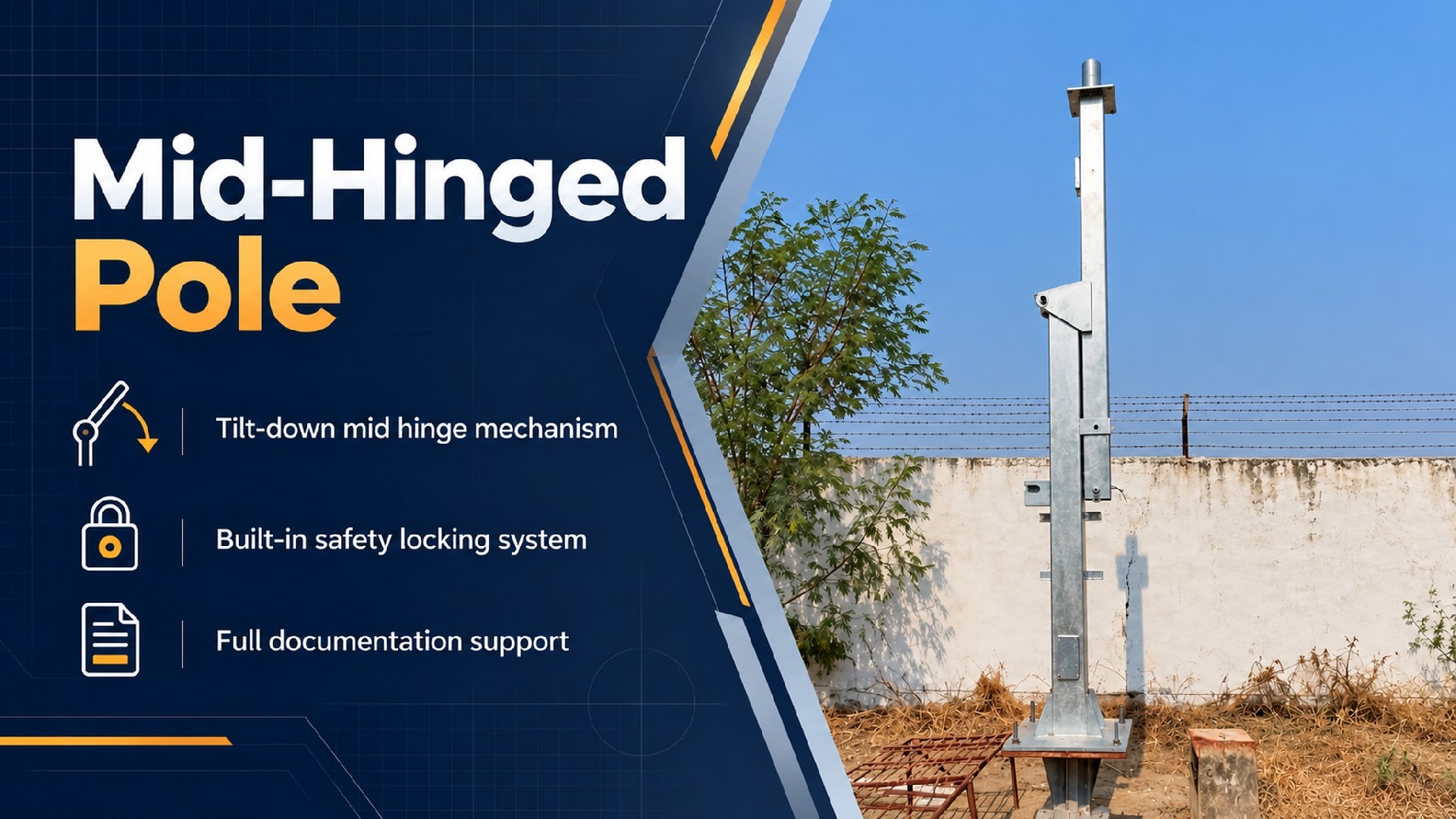
Product Overview
Mid-section pivot, counterbalanced leverage, and rope-assisted operation.
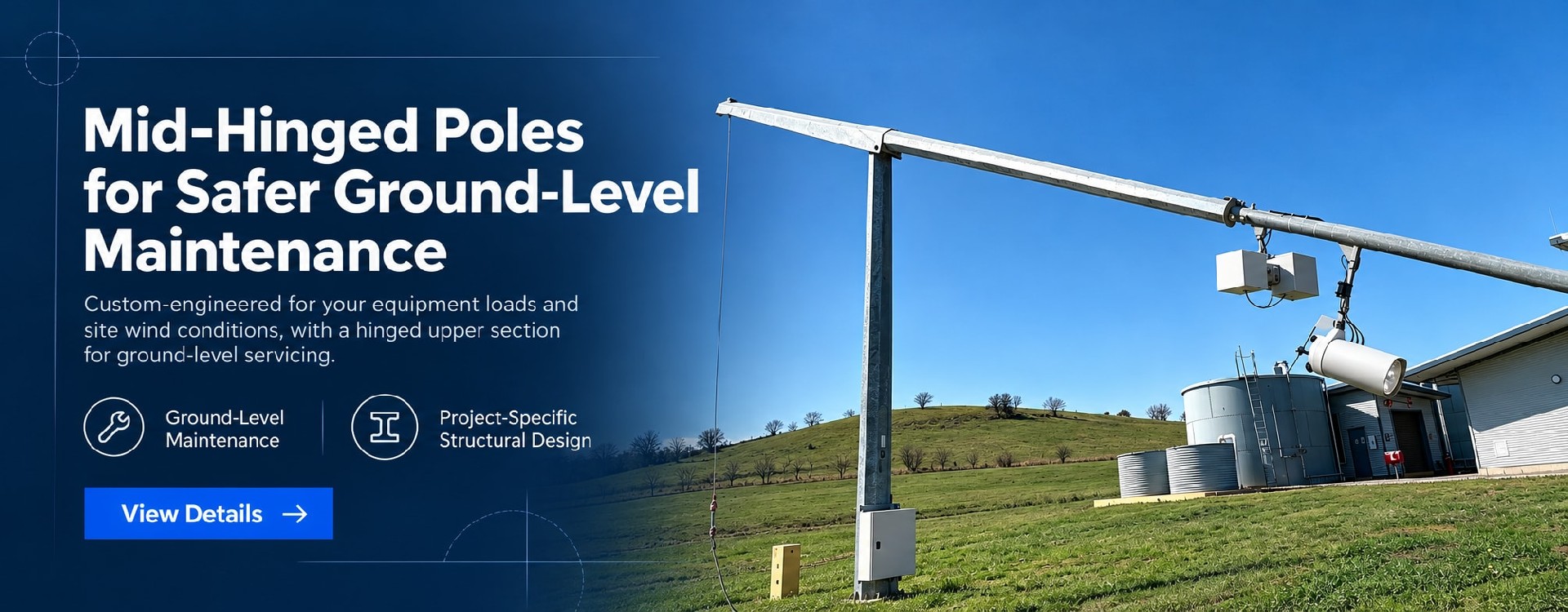
The upper shaft folds down parallel to the fixed lower section, bringing the luminaire to an ergonomic, accessible height while maintaining zero lateral swing radius. The lower shaft, foundation, access hatch, and internal cabling remain undisturbed throughout the cycle.
The Engineering Constraint: Eliminating the Swing Radius
When a standard base-hinged pole lowers, it sweeps a 180-degree arc clearance equal to its full height. While viable for wide highway verges, this clearance is frequently unavailable in constrained environments:
▶Narrow median strips: Lowering intrudes into active traffic lanes or strikes central barriers.
▶Overhead obstructions: Low bridges, tunnel portals, and overhead utility lines restrict both vertical and horizontal movement.
▶Architectural and urban obstacles: Adjacent buildings, property walls, overhead signage, and mature street trees leave no lateral clearance.
▶Restricted industrial zones: Narrow alleys in historic districts, industrial pipe racks, and confined mining sites preclude the use of heavy access equipment or swing zones.
Mid-hinged poles are engineered specifically to overcome these clearance limitations—not as a cost-reduction measure for logistics. By locating the pivot at the midpoint, the lower shaft remains upright and stationary while the upper section pivots down against it via a counterbalanced lever mechanism, lowering the luminaire head to a manageable height of 1.5 to 2.5 meters. The entire lowering and raising sequence is contained strictly within the pole’s own footprint.
| Result | Concrete Change |
Folding within footprint | No fan-shaped clearance required; narrow medians can be accommodated |
Lower section completely static | Foundation, access hatch, earthing bridging and cable entry position unchanged; no cable service-loop allowance needed |
One operator, one rope, no power | No winch day-rate, no hydraulic power pack, no working at height permits required |
| Minimal mechanism | Simple hinge pin + counterweight balance + locking pin; low part count for maintenance-free reliability |
The alternative solutions in this category involve minimal cost differences, meaning the economic argument should not center on "saving crane hire." Instead, the focus must be on installation feasibility: in clearance-constrained locations, a conventional fixed pole either forces the abandonment of ground-level maintenance or introduces a permanent working-at-height liability. A mid-hinged pole allows an entire road section to adopt a uniform, ground-level servicing standard, significantly streamlining long-term maintenance management.
1. A Stationary Lower Section Delivers the Core Engineering Advantage
When a base-hinged pole lowers, the cable entry and access hatch move along with it, requiring either a service-loop allowance or a flexible routing structure—which introduces long-term fatigue and wear risks. In contrast, with a mid-hinged pole, the lower section, foundation, access hatch, and earthing terminal remain entirely stationary. The cable route remains continuous and undisturbed. This is the primary feature endorsed by maintenance departments.
2. Two-Stage Locking to Prevent Operator Error
The working position is secured by a heavy-duty locking pin and bolted mechanism, with provisions for a padlock. A dedicated anchor point is provided in the lowered position to prevent wind-induced movement. Before release, operators must isolate the power supply and verify that the counterweight fixings are secure—a mandatory protocol highlighted on the cover of the operation manual and frequently audited by overseas project supervisors.
3. Counterweight Principle for Single-Operator Handling
The weight of the upper section is offset by an integrated balancing counterweight. Operators require only a ∅12 mm double-braided rope (minimum length 1.5× pole height), pulled from a safe position outside the swing arc. The complete lowering or raising cycle takes 30–60 seconds, requiring no specialized tools.
4. Maintenance-Free Hinge Design
The hinge pin utilizes high-grade stainless steel featuring double-lip seals and a grease fitting, with exposed components receiving the same surface treatment specification as the pole body. An earth-continuity bonding terminal is installed across the hinge to maintain unbroken whole-pole grounding.
☛The hinge is located approximately 1.8 m above ground; accessibility is less convenient than a base hinge. We recommend a routine inspection of the hinge pin and locking components every 6 months.
☛Do not alter counterweights, and do not change luminaire weight or quantity without authorisation—any such change directly affects balance and the safe operating range. Any modification requires written confirmation from our engineering team.
☛In the folded position, the upper section cantilevers outward. In high-wind zones, we recommend adding a tie-down anchor point.
☛A visible transition exists at the two pole sections. For visually sensitive routes, a tapered transition cover with matching powder coating is available.
Physical Deliverables
- Pole and hinged mechanism supplied as a complete set (including counterweights)
- One operating rope + padlock
- Wear-parts kit (seals, pins, fasteners)
Installation Documents
- Foundation and anchor-bolt drawing
- Rope operation training video
Technical Verification
- Hinge pin and locking component calculation notes
- Wind-load verification report
- Galvanising report and MTC
After-Sales Support
- Spare-part codes and long-term supply commitment
(Ht = Height | Ctrl = Control | Prot = Corrosion Protection)
▶Narrow median strip
Ht: [6–10 m] | Ctrl: Rope + counterweight | Prot: Hot-dip galvanising
▶Under bridges/interchanges
Ht: [6–9 m] | Ctrl: Rope + counterweight | Prot: Galvanising + powder coating
▶Overhead lines / old lanes
Ht: [5–8 m] | Ctrl: Rope | Prot: Hot-dip galvanising
▶Rail corridors (restricted)
Ht: [8–12 m] | Ctrl: Rope + padlock | Prot: Hot-dip galvanising / C4
▶Mining/plant sites
Ht: [6–10 m] | Ctrl: Rope | Prot: Double-layer C4
▶Coastal towns
Ht: [6–9 m] | Ctrl: Rope | Prot: C5-M / optional SS hinge pin
Jump to : Commercial Terms | FAQ | Delivery Commitment
| Item | Parameter |
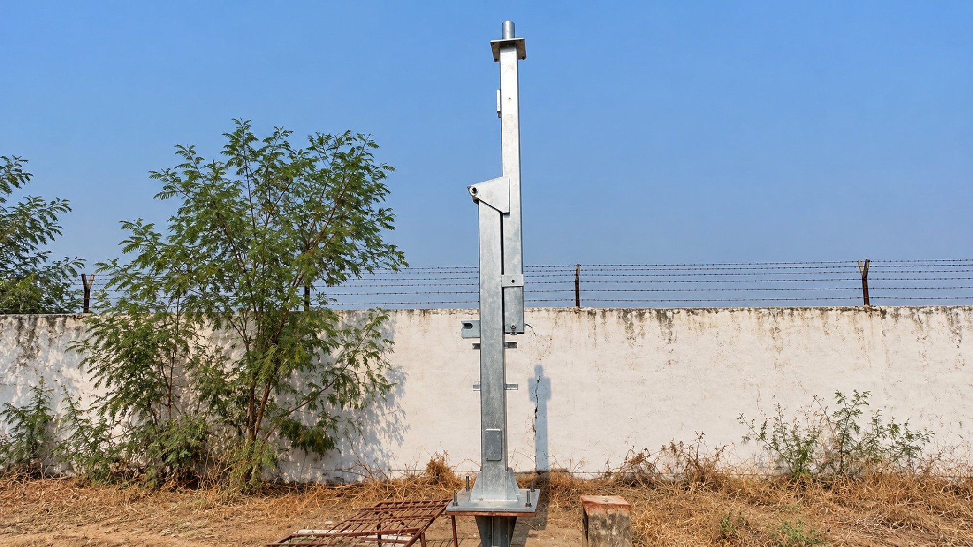
| Structural Type | Mid-section hinged; lower section vertical and fixed; upper section folds down |
| Hinge Position | Typically 1/2 of overall pole height. Custom hinge position from 1/3 to 1/2 available via structural calculation. |
| Height Range | 4-12m(above this range, evaluate on a case-by-case basis) |
| Section/Material | Octagonal tapered or circular / Carbon Steel Q235B/Q355B |
| Manufacturing tolerances | Flange flatness ≤ 0.2mm, shaft straightness ≤ L/750, bolt hole deviation ± 1.5mm |
| Pole Section Connection | 1. Base flange connection to foundation. 2. Mid-section hinge assembly with locking flange, for upper-section lowering and ground-level servicing. |
| Luminaire & Accessory Load | ≤ 40 kg(standard), windage area ≤ 0.4 m²(subject to final design) |
| Operation | Manual rope pull (single operator at ground level) |
| Rope Specification | Ø12 mm double-braided rope, length ≥ 1.5 × pole height |
| Lowering/Raising Time | Full cycle: 30–60 s (manual, no special tools required) |
| Wind Load Rating | Operating state: 37 m/s (≈133 km/h); Folded state: 20 m/s (≈72 km/h) |
| Corrosion Protection | Hot-dip galvanising ≥ 85 µm; optional galvanising + powder coating / C5-M |
| Hinge Pin | Stainless steel/hot-dip galvanised steel + sealing + grease fitting; earthing bridge at hinge |
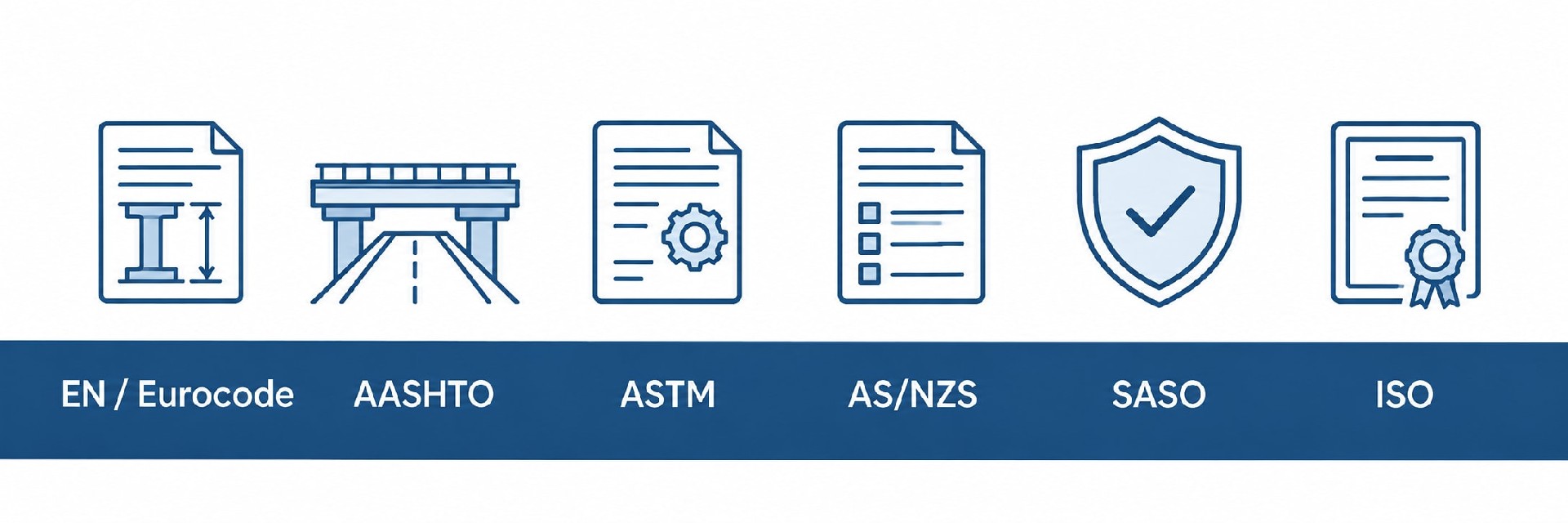
Supported by an ISO 9001:2015 quality management system, we can adapt pole design, manufacturing quality control, corrosion protection, and technical documentation to project-specific standards and local requirements, supporting overseas project approval, procurement, and acceptance.
Structural Design & Wind Load Verification: Structural calculations can be performed in accordance with EN 40 / EN 1993, AASHTO, applicable AS/NZS standards, SASO requirements, or other project-specified codes. Design verification can incorporate site wind speed, equipment loads, mounting height, and environmental conditions.
Welding & Manufacturing Control: Welding procedures and quality control can be adapted to applicable EN 1090 execution requirements and ISO 3834 welding quality requirements, with corresponding process, inspection, and documentation controls implemented as required by the project.
Corrosion Protection: Hot-dip galvanizing and coating systems can be configured according to the project environment and required service life. Treatments can be specified to ISO 1461, ASTM A123/A123M, or other project requirements for standard outdoor, coastal, high-humidity, and high-salinity environments.
Engineering Documentation Support: Project documentation can include structural calculation reports, shop drawings, material certificates, welding records, galvanizing or coating inspection reports, dimensional inspection records, and factory quality documentation for client, consultant, or EPC review.
Multi-Market Project Support: We support project requirements across Europe, North America, the Middle East, and Asia-Pacific. Applicable design standards, inspection requirements, and document packages can be defined according to the project location and technical specification.
Term | Detail |
| Customization | Supported — MOQ 1 unit |
| Lead time | Standard configuration: 3–4 weeks / Custom-engineered configuration: 4–5 weeks |
| Payment terms | 30% T/T advance · 70% before shipment · L/C at sight accepted |
| Trade terms | EXW: Specify named place FOB: Specify port of shipment CFR / CIF: Specify destination port |
| Inspection support | Third-party factory inspection by SGS / BV / TÜV welcomed |
| Samples | Available — sample cost credited against first production order |
⚠️Safety Warning
☛The mid-hinged pole operates relying on a precisely calibrated counterbalance system. Do not add or remove counterweights, or modify the quantity, model, or weight of luminaires without the manufacturer’s approval. Any unauthorized alteration may break balance and lead to severe safety hazards.
☛Always cut off power to the lighting fixtures before lowering or raising the pole.
☛Do not operate the pole if any component of the counterweight or hinge assembly is damaged. Operation must be performed by trained personnel; solo operation is prohibited.
☛Do not perform lowering/raising operations when wind speed exceeds 12 m/s.
🛠️Equipment Required
- Specified high-strength double-braided rope (minimum diameter ≥12 mm)
- Rigger's gloves for slip and cut resistance, to secure grip and protect hands during pulling
- Secure anchoring point: fasten the rope firmly to a robust fixed structure such as a vehicle crash barrier
📥Operation Procedure
①Pre-operation Inspection: Check hinge lubrication, integrity, and proper engagement of the safety locking pin, and confirm the wire rope has no wear or damage.
②No-load Test: Complete a full lowering and raising cycle before mounting luminaires. Verify smooth hinge movement with no abnormal noise or jamming.
③Locking & Securing: Once the pole is raised to the vertical working position, fully engage and lock the hinge locking flange and safety pin to firmly secure the upper pole section.
④Post-reset Inspection: After raising and locking the pole, recheck bolt torque on locking flanges and confirm no looseness or abnormal displacement of the upper pole.
We provide custom wind-load calculation reports, 2D CAD drawings, installation manuals, and tender technical documents to support your global project approvals and customs clearance.
For general-purpose technical handbooks and safety guidelines, please visit our Download Center→
🚀 Rapid Delivery: Standard orders ship in 3–5 weeks. Custom schedules available.
🔒 Secure Financing: Staged payments via T/T or L/C ensure financial control.
👤 Dedicated Management: A dedicated project manager provides real-time production updates.
📦 Reliable Packaging: Moisture-proof and shock-resistant packaging ensures safe container and ocean transit.
📄 Technical Documentation: Full engineering files, including structural calculations, ship with every order.
Operation & Safety
Q1: Can I adjust the counterweights myself? Can I switch to a heavier LED luminaire?
A: No. Counterweights are factory-matched to the specified luminaire weight and windage area. Any unauthorised change upsets the balance and makes operation unsafe. If a luminaire change is required, contact us for recalculation and counterweight replacement.
Q2: Can one person really pull it down? How long should the rope be?
A: Yes, only when the pole is within the rated top load and height ≤8 m. The counterweights offset most of the upper-section weight, so a single trained operator can lower the pole. Poles over 8 m or with heavy top equipment require two trained operators. The rope should be no less than 1.5 times the pole height, and the operator must stand well outside the swing arc. On first use, we recommend anchoring the rope to a fixed point to get a feel for the motion.
Structure & Clearance
Q3: Will it strike the lower section or surrounding objects when it comes down?
A: Not when operated within the designed swing arc. Guide limiters and travel stops confine the trajectory to the approved range. Please declare surrounding obstructions at the ordering stage so we can fix the swing direction on the general arrangement drawing.
Q4: How high is the luminaire head when folded down?
A: The luminaire head rests at approximately 1.5–2.5 m above ground — within easy reach. Once lowered, insert the retaining pin and secure the tie-down strap to prevent wind-induced movement.
Selection Notes
Q6: Is it more expensive than a base-hinged pole?
A: In the same height range, prices are broadly similar; the mid-hinged type carries a modest premium for the hinge assembly and counterweight set. Selection should be driven by clearance, not price: if you have a clear swing arc, choose base-hinged; if not, choose mid-hinged.
Q7: What is the maximum practical height?
A: The standard range covers 5–12 m. Above 15 m requires case-by-case evaluation due to counterweight mass, hinge-pin loading, and operational safety; such cases are usually better served by a base-hinged or heavy-duty solution.
Specifications are typical values for reference only under standard conditions — not a guarantee. Final performance shall be determined by project design calculations and factory test reports. Consult a local engineer before specifying.