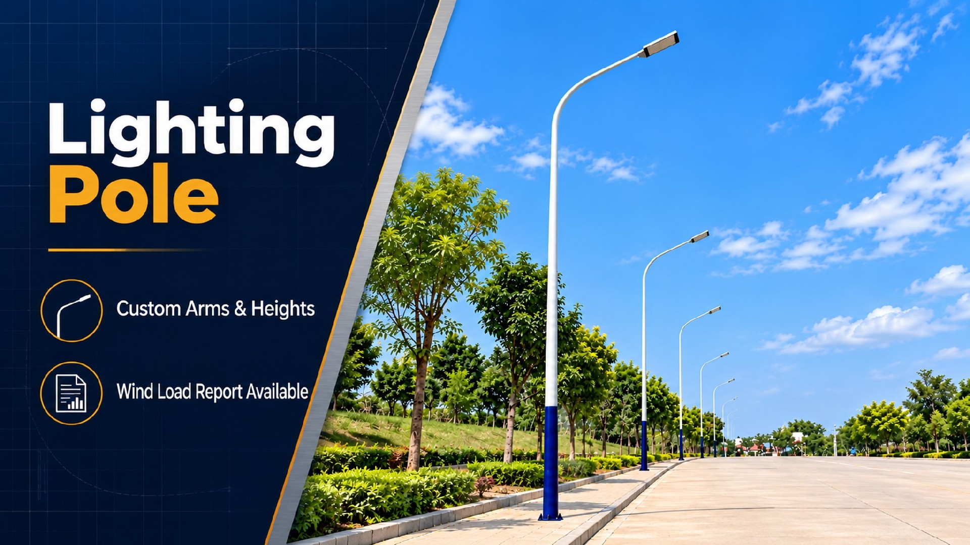
Project Delivery Capability
| Item | Detail |
| Monthly Capacity | Up to 2,000 poles |
| Largest Single-Project Delivery | 5,000 poles — 99% on-time delivery rate |
| Markets Served | Large-scale infrastructure projects globally |
| Standard Lead Time | 3–5 weeks from drawing approval |
| MOQ | 1 pole — sample cost credited against first production order |
Our Positioning: We are not the factory that makes the best sample — we are the factory that makes the 500th pole identical to the 1st.
1. The 500th Pole = The 1st Pole: Batch Consistency System
Our manufacturing system does not rely on individual craftsmen. It is built on standardized tooling, automated welding, and Statistical Process Control (SPC). The process capability index (Cpk) for all critical dimensions is consistently maintained above 1.33, with historical batch defect rates below 0.5%.
What this means for you: When you order 800 poles, every single one arrives with flange flatness, shaft straightness, and coating thickness within the same tolerance band. Your installation crew will never encounter mismatched fittings or need on-site modifications. Project sign-off — first time, every time.
2. Save 20–30 Minutes of Installation Time Per Pole
| Parameter | Our Standard | Industry Norm |
| Flange flatness | ≤ 0.3 mm | ≤ 0.5 mm |
| Bolt hole positional tolerance | ≤ ± 0.5 mm | ≤ ± 1.0 mm |
Field Performance: Anchor bolts slide in without forcing. The base plate seats flush on first contact. No shimming required for plumb adjustment.
What this means for you: On a 500-pole project, this translates to approximately 167–250 labor-hours saved. At North American/European labor rates, installation savings alone range from $6,000 to $25,000.*
*Actual savings depend on local labor rates, crew composition, and site conditions. Figures are provided for project evaluation purposes only and do not constitute a guaranteed return.
3. Lower Total Landed Cost Than Local Procurement
It is not just the ex-works price that is competitive — cost advantages extend across the entire chain from factory to foundation:
-Automated production drives down unit manufacturing cost
-Nested transport design reduces freight cost by 40–60%
-Precision flanges cut installation labor hours
-Batch consistency eliminates rework and warranty claims
What this means for you: Even if the unit price is comparable to your local supplier, your total installed project cost remains significantly lower.
4. Environment-Matched Corrosion Protection — Multi-Material Options for 20+ Year Service Life
Corrosion protection is specified according to ISO 12944 environmental classification (C3 / C4 / C5-M):
-Carbon steel: Hot-dip galvanized (≥ 85 μm) + electrostatic powder coating (≥ 80 μm) .
-Stainless steel: Relies on base-metal passivation for corrosion resistance; optional RAL powder coating available.
-Aluminum alloy: Anodizing or powder coating options available
-All materials deliver long-term service capability when matched to the appropriate environment and maintained per specification.
5. Arrive on Site, Install Immediately — Zero Field Fabrication
Every pole ships with factory-preinstalled luminaire arms, waterproof junction boxes (IP65), internal cable routing channels, grounding terminals, and precision-machined base flanges. The installation crew bolts it down and moves on — no on-site drilling, welding, or cutting required.
1. Batch Consistency: Our Core Manufacturing Edge
Why Batch Consistency Is the #1 Decision Factor in Lighting Pole Procurement
Lighting pole projects involve hundreds or even thousands of units. Any factory can produce a single good sample — but inter-batch quality variation is the real killer on large-scale projects:
-Flange flatness varies → some poles mount plumb, some tilt → the entire roadway looks like a roller coaster
-Bolt hole positions drift → some poles install directly, others require on-site reaming → installation schedule becomes unpredictable
-Coating thickness is uneven → some poles last 20 years without rust, others show corrosion in 5 → warranty claims become unforecastable
This variation exists at local manufacturers in Europe and North America as well — and because labor costs are high, batch defects trigger extremely expensive rework.
2. How We Achieve "500 Poles, Identical to 1"
| Control Point | Specific Measure | Quantified Result |
| Plate leveling | CNC leveling machine eliminates residual stress from coiled stock | Flatness deviation ≤ 1 mm/m before forming |
| Press braking | CNC press brake — single-pass forming eliminates cumulative error from multi-pass manual bending | Taper deviation ≤ 0.5°, straightness ≤ L/1000 |
| Flange alignment | Dedicated fixtures lock flange position — no manual alignment required | Flange flatness ≤ 0.3 mm, hole position tolerance ≤ ± 0.5 mm |
| Longitudinal seam welding | Submerged Arc Welding (SAW) — travel speed, current, and voltage automatically regulated | Penetration consistency Cpk ≥ 1.33 |
| Flange welding | Automated welding station with precisely controlled heat input | Post-weld distortion ≤ 0.2 mm — no straightening required |
| Coating thickness | Online thickness gauge with real-time feedback to adjust spray parameters | Batch thickness range ≤ 10 μm |
| Final inspection | 100% dimensional inspection + coating adhesion spot testing | Outgoing defect rate < 0.5% |
Key Figures
-Flange flatness: ≤ 0.3 mm (industry norm: ≤ 0.5 mm)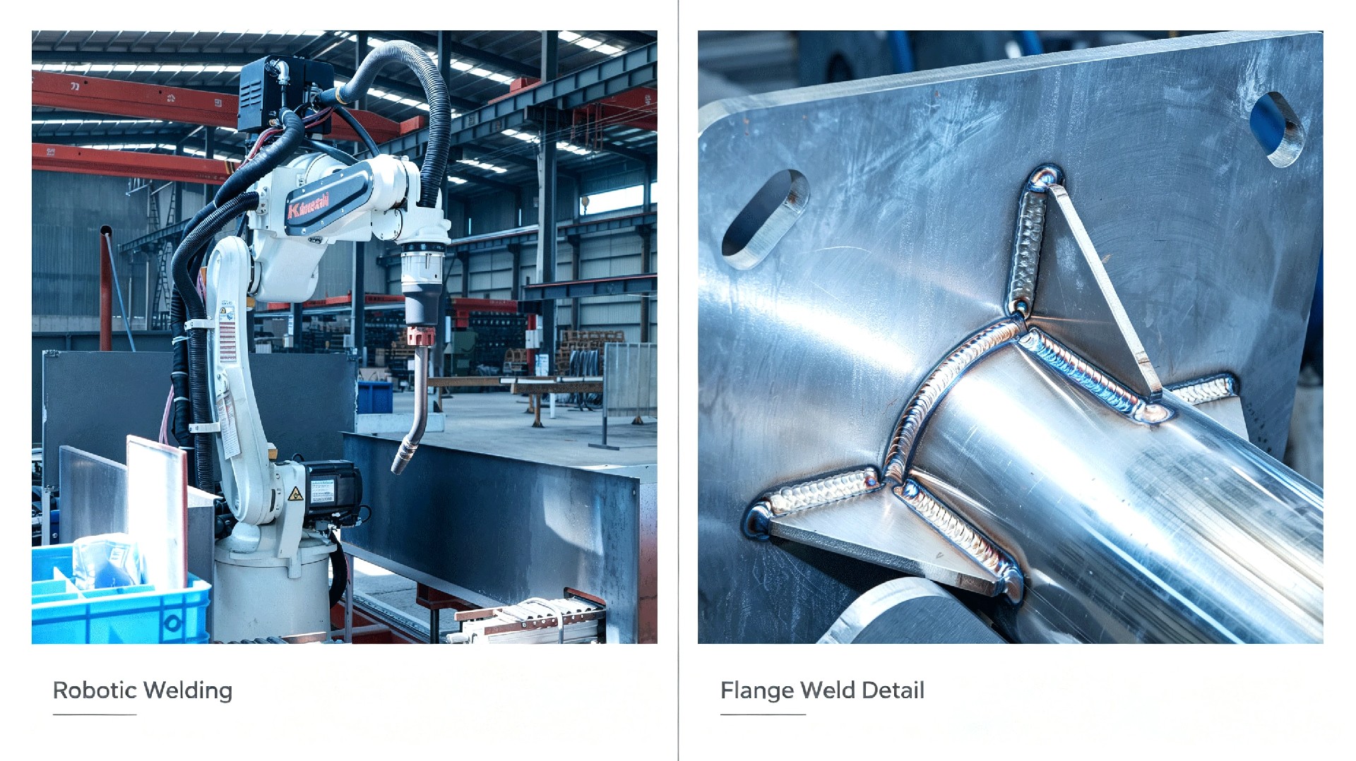
-Bolt hole positional tolerance: ≤ ± 0.5 mm (industry norm: ≤ ± 1.0 mm)
-Shaft straightness: ≤ L/1000
-Batch defect rate: < 0.5%
-Process capability index Cpk: ≥ 1.33 (all critical dimensions)
3. Installation Efficiency: How Precision Translates to Real Cost Savings
⑴ Flange Quality vs. Installation Time
| Flange Quality Level | Field Performance | Installation Time Per Pole |
| High precision (our standard) | Bolts slide in directly, base plate seats flush, no shimming needed | Baseline time T |
| Industry standard | Some bolts require reaming, base plate needs shimming for level | T + 20–40 min |
| Low precision (small-shop level) | Extensive reaming/redrilling, base plate severely out-of-flat requiring grinding | T + 40–90 min |
⑵ Project-Level Cost Impact Analysis
Basis: 500 poles, 6–8 m standard municipal poles
| Cost Item | High-Precision Flange (Ours) | Additional Cost from Industry-Standard Flange | Notes |
| Installation time per pole | ~30 min (baseline T) | + 25 min/pole | No reaming, no shimming, no hole alignment |
| Total labor-hour difference (500 poles) | — | + ~208 hours | 25 min × 500 ÷ 60 |
| North American labor cost impact | — | + $8,300–$16,600 | 25 min × 500 ÷ 60 |
| European labor cost impact | — | + €7,300–€12,500 | €35–60/hour |
| Touch-up painting after reaming | Zero reaming-related touch-up | North America: $2,500–$7,500 (500 poles) / Europe: €2,000–€6,500 | $5–15/pole (NA), €4–13/pole (EU) |
| Schedule delay risk | Low | Medium | Rework makes schedule unpredictable |
Notes:
①The 25-minute per-pole time differential is an estimate based on typical field installation scenarios. Actual times vary with site conditions, crew experience, and foundation quality.
②Labor rates reference average market rates for certified installation crews in North America and Western Europe (2025–2026). Eastern Europe, the Middle East, and other regions may differ.
③Touch-up painting costs cover materials and labor for recoating areas where galvanizing or powder coating was damaged by on-site reaming. Rate differences between North America and Europe reflect local labor cost levels.
④All figures are provided for reference only and do not constitute any guarantee. Actual project savings depend on specific site conditions.
4. Full Supply-Chain Cost Structure
| Beyond the Factory Gate — Total Cost Breakdown from Factory to Foundation | ||
| Cost Dimension | Our Advantage | Impact for Integrators |
| Ex-works price | Automated production + high material utilization + low defect rate → competitive EXW price | Direct procurement cost controlled |
| Freight cost | Poles above 6 m use telescopic nesting design — 40HQ container loading increased by 40–60% | Per-unit freight cost significantly reduced |
| Installation cost | Precision flanges → 20–30 min saved per pole → thousands of dollars saved on batch projects | On-site cost predictable |
| Warranty cost | Batch defect rate < 0.5% → warranty claims near zero | Hidden risk cost minimal |
| Project management cost | Consistent quality → no per-pole re-inspection → reduced or waived incoming inspection | Management bandwidth freed |
Total Landed Cost = EXW Price + Freight + Installation + Warranty Reserve + Management Overhead
We have cost advantages at every stage. The result: even if the unit price is comparable to your local supplier, your total project cost is still lower.
| Transport Efficiency Detail | |||
Pole Height | Transport Method | 40HQ Loading | Freight Savings vs. Full-Length |
| 2–4 m | Full-length nested Full-length nested | 40–60 pcs | — |
| 4–6 m | Full-length nested | 20–35 pcs | — |
| 6–8 m | 2-section nested | 12–18 pcs | ~40–50% |
| 8–12 m | 2–3-section nested | 8–12 pcs | ~50–60% |
Quick jump: Commercial Terms | FAQ | Luminaire Adaptability
We do not apply a one-size-fits-all approach. Different environments require different protection grades — neither over-specified (wasting budget) nor under-specified (leaving risk).
| Environment Class | Typical Applications | Carbon Steel (Q235B / Q355B) | Stainless Steel (SS304 / SS316L) | Aluminum Alloy (6063-T5 / 6061-T5/6061-T6 / 6082-T6) |
| C3(Moderate) | Inland urban roads, rural highways | HDG ≥ 85 μm + standard powder coating ≥ 80 μm | SS304 brushed + electrolytic passivation (optional RAL coating) | Anodizing ≥ 15 μm (or standard powder coating) — all three alloys available |
| C4(High) | Industrial zones, urban arterial roads (de-icing salt areas) | HDG ≥ 85 μm + weather-resistant powder coating ≥ 80 μm | SS304 brushed + electrolytic passivation (optional RAL coating) | Anodizing ≥ 25 μm + sealing (or weather-resistant powder coating) |
| C5-M(Marine) | Coastal roads, ports, sea-crossing bridge approaches | HDG ≥ 100 μm + marine-grade pure polyester powder ≥ 80 μm (salt spray ≥ 1,440 h) | SS316L brushed + electrolytic passivation (optional RAL coating) | Anodizing ≥ 25 μm + PVDF fluorocarbon coating (marine grade) — 6061-T6 / 6082-T6 recommended, 6063-T5 not recommended |
| Parameter | Standard Carbon Steel Pole Specification |
| Pole Height | 3 m – 12 m (Standard Series) |
| Material | Carbon steel (Q235B / Q355B), 201/304/316L stainless steel, aluminum alloy (6063-T5/6061-T5/6061-T6/6082-T6) |
| Wall Thickness | 3mm - 8mm(Customized per height & load) |
| Base Flange | Precision-machined, flatness ≤ 0.3 mm, bolt hole tolerance ≤ ± 0.5 mm |
| Color | Standard RAL colors available; custom color matching supported |
| Junction box | IP65 rated, factory-integrated |
| Cable entry | Hinged access door with internal cable routing channel |
| Grounding | Dedicated grounding terminal at base |
Supported by an ISO 9001:2015 quality management system, we can adapt pole design, manufacturing quality control, corrosion protection, and technical documentation to project-specific standards and local requirements, supporting overseas project approval, procurement, and acceptance.
Structural Design & Wind Load Verification: Structural calculations can be performed in accordance with EN 40 / EN 1993, AASHTO, applicable AS/NZS standards, SASO requirements, or other project-specified codes. Design verification can incorporate site wind speed, equipment loads, mounting height, and environmental conditions.
Welding & Manufacturing Control: Welding procedures and quality control can be adapted to applicable EN 1090 execution requirements and ISO 3834 welding quality requirements, with corresponding process, inspection, and documentation controls implemented as required by the project.
Corrosion Protection: Hot-dip galvanizing and coating systems can be configured according to the project environment and required service life. Treatments can be specified to ISO 1461, ASTM A123/A123M, or other project requirements for standard outdoor, coastal, high-humidity, and high-salinity environments.
Engineering Documentation Support: Project documentation can include structural calculation reports, shop drawings, material certificates, welding records, galvanizing or coating inspection reports, dimensional inspection records, and factory quality documentation for client, consultant, or EPC review.
Multi-Market Project Support: We support project requirements across Europe, North America, the Middle East, and Asia-Pacific. Applicable design standards, inspection requirements, and document packages can be defined according to the project location and technical specification.
Industrial-grade pre-engineered luminaire arms and mounting brackets, precisely matched to mainstream outdoor luminaires from global manufacturers based on your project specifications.
Compatible Luminaire Types:
North American Style Cobra Head LED Street Lights (Standard arm + slip-fitter / clamp mount)
Single / Double Cantilever Roadway LED Luminaires (Top-mounted flange plate)
Area Floodlights (Heavy-duty cantilever bracket)
Post Top / Garden Lights (Top flange plate)
All-in-One Solar Street Lights (Pre-configured mounting positions for PV panel brackets)
🔧 Precision Customization: Arm length, tilt angle, bracket structure, and cable entry points can all be fully customized according to your luminaire specifications or CAD drawings. Arms and brackets feature high-precision laser cutting with dimensional tolerances within ±0.5 mm, with pre-fabrication and anti-corrosion treatments completed entirely in the factory — arriving ready for immediate installation, eliminating on-site cutting or welding that damages protective coatings.
| Scenario | Recommended Configuration |
| Municipal arterial roads | 10–12 m, dual arm, C4 corrosion protection, S235JR carbon steel |
| Residential / community roads | 6–8 m, single arm, C3 corrosion protection, S235JR carbon steel |
| Industrial parks/facility grounds | 8–10 m, dual arm, C4 corrosion protection, S235JR carbon steel |
| Rural / township roads | 4–6 m, single arm, hot-dip galvanized (economy spec), S235JR carbon steel |
| Coastal / highly corrosive zones | 6–12 m, C5-M corrosion protection, 316L stainless steel optional |
Term | Detail |
| Customization | Supported — MOQ 1 unit |
| Lead time | Standard configuration: 3–4 weeks / Custom-engineered configuration: 4–5 weeks |
| Payment terms | 30% T/T advance · 70% before shipment · L/C at sight accepted |
| Trade terms | EXW: Specify named place FOB: Specify port of shipment CFR / CIF: Specify destination port |
| Inspection support | Third-party factory inspection by SGS / BV / TÜV welcomed |
| Samples | Available — sample cost credited against first production order |
⚡ Galvanic Corrosion Prevention: Carefully match fastener materials. When connecting dissimilar metals, use isolating non-conductive gaskets. (Service option: Pre-installed nylon/EPDM isolation gaskets available upon request).
💧 Drainage & Sealing: Keep base drainage openings unobstructed; hand-hole covers and seals must remain intact. Never bury flange plates underground.
🛡️ Surface Protection: Protect passivated and brushed surfaces from mechanical scratches during installation. Local touch-up passivation treatment is required for any damaged areas.
🔌 Grounding Requirement: Complete proper grounding and equipotential bonding in compliance with local electrical codes.
🏗️ Foundation Rules: Anchor bolts and concrete foundations must satisfy local wind-load requirements. Erect poles only after concrete has fully cured.
We provide custom wind-load calculation reports, 2D CAD drawings, installation manuals, and tender technical documents to support your global project approvals and customs clearance.
For general-purpose technical handbooks and safety guidelines, please visit our Download Center→
🚀 Rapid Delivery: Typically ship within 3–5 weeks.
💰 Volume Pricing: Tiered pricing structures available for bulk orders.
📦 Export-Grade Packaging: Moisture-proof and shock-resistant packaging optimized for safe container loading.
📊 Real-Time Tracking: Dedicated project managers providing regular production progress updates.
Q1: Will large‑size floodlights cause excessive pole sway?
A: Pole sway is determined by pole height, wall thickness, design wind speed, and luminaire weight. Our standard lighting poles adopt deflection ≤ H/200 under design wind load. Please provide your floodlight weight, dimensions, and mounting position. We will conduct a structural check and confirm if the standard pole works, or recommend reinforced wall thickness if needed. We can also supply a structural calculation sheet for tender submission.
Q2: Which LED luminaire brands are compatible with your poles?
A: Our luminaire arms use a universal mounting interface design, compatible with all mainstream LED street light mounting methods:
Clamp-on mounting: Fits φ48–φ76 mm arm diameters
Flange mounting: Top mounting plate custom-drilled to match luminaire base flange hole pattern
Spigot mounting: Luminaire inserts directly into arm end, secured by set bolt
If you use a specific luminaire brand, provide the mounting drawing, and we will complete interface adaptation before shipment.
Q3: Can you prefabricate pole top brackets to fit my lighting fixtures?
A: Yes. We custom-machine top mounting brackets and pre-drill hole patterns according to your CAD drawings. Factory prefabrication eliminates on-site cutting, welding, and re-drilling, protects coating integrity, and speeds up site installation. Our brackets support most mainstream floodlights and street lamp brands.
Q4: Can the flange bolt hole pattern be customized to match our foundation drawings?
A: Yes. We offer two options:
Standard hole patterns: Covering mainstream standards across European, North American, Middle Eastern, and Asian markets.
Custom hole patterns: Drilled entirely to your foundation drawing or luminaire mounting requirements. All dimensions are verified against your CAD data before production begins.
Q5: Can you provide base flange loading data for civil foundation design?
A: Yes. We supply a complete foundation design data package: base reactions (overturning moment, shear force, axial force), flange drawing (bolt layout), anchor bolt specifications (grade, diameter, embedment depth), and base plate thickness. All data is derived from the same structural calculation model used for the pole design.
Q6: How do I select the right pole material and anti‑corrosion coating for my project environment?
A: We provide carbon steel, stainless steel, and aluminium alloy options, matched to ISO 12944 C3 / C4 / C5‑M corrosion classes.
- C3 Inland environment: Carbon steel duplex coating or standard aluminium
- C4 Industrial / mild coastal area: Duplex hot‑dip galvanizing + powder coating carbon steel or aluminium with seal treatment
- C5‑M Marine salt‑spray zone: SS316L or aluminium with PVDF coating (6061‑T6 / 6082‑T6 recommended, 6061‑T5 not suggested)
Tell us your site location and environment; we will give a targeted material proposal.
Specifications are typical values for reference only under standard conditions — not a guarantee. Final performance shall be determined by project design calculations and factory test reports. Consult a local engineer before specifying.