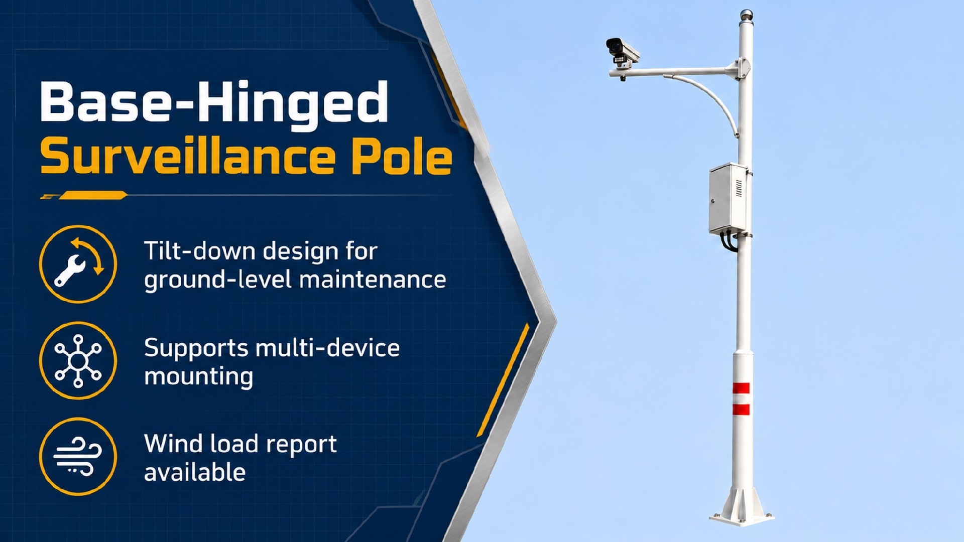
Ground-Level Maintenance with Less Reliance on Access Equipment
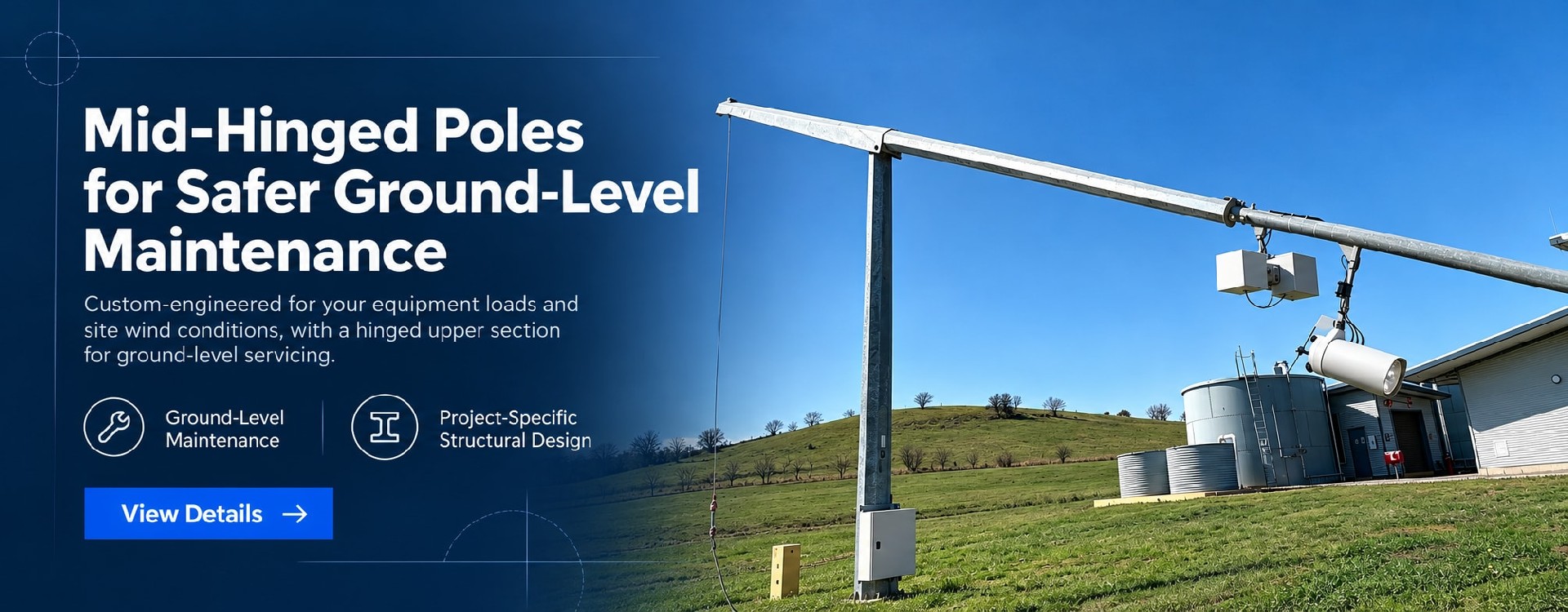
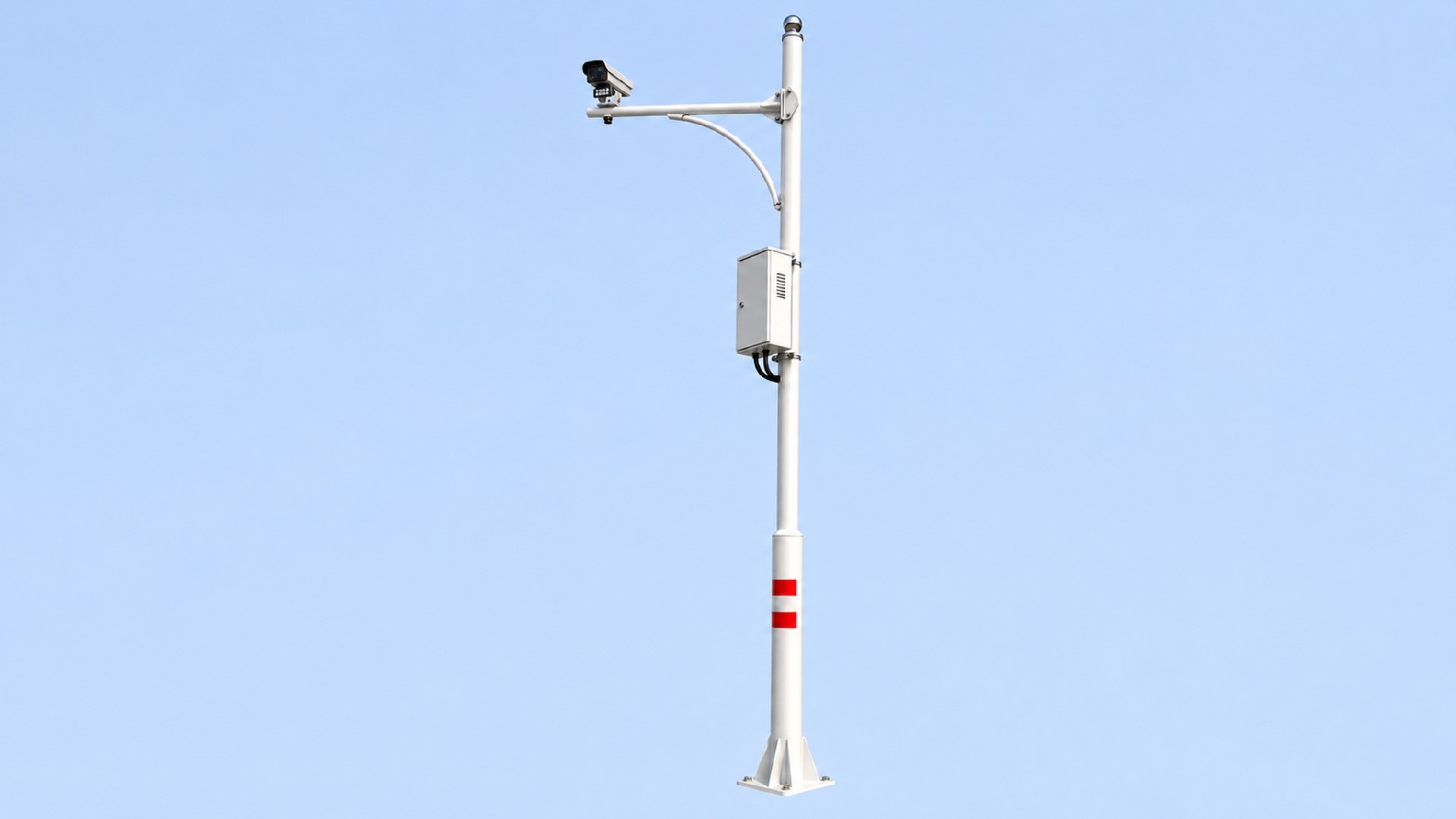
A base-hinged design allows the pole to tilt down in a designated direction, bringing cameras and other pole-mounted equipment within reach for maintenance. This reduces reliance on mobile elevating work platforms and access vehicle callouts for routine servicing.
The pole structure, hinge assembly, and raising and lowering equipment are specified to suit equipment loads, site wind conditions, and available lowering space. Suitable for surveillance locations where vehicle access is restricted, or access equipment is costly to mobilise.
Ground-Level Maintenance · Project-Specific Structural Design · Custom Equipment Mounts
[ Request a Project Quote ] [ Request Technical Documents ]
Easier Equipment Access at Hard-to-Service Locations
| Application | Practical Benefit |
| Remote and Unattended Sites | Provides access to pole-mounted equipment while reducing the need to mobilise access equipment over long distances |
| Oil and Gas Pipelines, Oilfields and Mining Sites | Supports surveillance and communication equipment, with the lowering arrangement planned around site conditions |
| Roadside and Operational Areas | Facilitates equipment cleaning, inspection and replacement where sufficient lowering clearance and a controlled work area are available |
| Industrial Facilities and Commercial Sites | Simplifies routine servicing and upgrades to cameras, sensors and communication equipment |
Check Lowering Clearance Before Installation
The site must accommodate the pole’s full lowering path, the equipment servicing position and a suitable exclusion zone. Fences, buildings, overhead lines, roads and projecting equipment all affect pole positioning and the direction of lowering.
Where space is restricted, the lowering path is obstructed, or an exclusion zone cannot be established, a mid-hinged pole, equipment lowering system or another maintenance arrangement may be more suitable. Roadside operations remain subject to site traffic management requirements.
1. Easier Access for Routine Maintenance
Once lowered and secured in the designated servicing position, cameras and other equipment can be cleaned, inspected, or replaced at an accessible working height. At sites with difficult vehicle access, this can reduce access equipment callouts and maintenance coordination costs.
2. Raising and Lowering Equipment Matched to the Load
The operating arrangement is selected according to pole weight, equipment weight, centre of gravity, and offset loads. Required personnel and operating limits are defined in the instructions for the approved configuration.
3. Designed for Structural Capacity and Equipment Stability
Structural design considers equipment wind area, mounting height, bracket outreach, and project wind loads. Pole-top deflection and rotation can be assessed against project requirements for long-range cameras, PTZ cameras and radar equipment.
4. Defined Requirements at Each Operating Stage
| Operating Stage | Key Requirements |
| Upright Service Position | Designed connections and locking arrangements secure the pole in position, with measures against loosening and unauthorised operation specified as required |
| Controlled Raising and Lowering | Compatible operating equipment controls pole movement in accordance with the prescribed procedure, operating wind limits and exclusion zone requirements |
| Maintenance Position | Designated supports or restraints secure the lowered pole and protect mounted equipment during servicing |
| Return to Service | Connections, cables and equipment mounts are checked after the pole is raised and locked; equipment alignment and calibration are verified where required |
[ Discuss Your Operating Requirements ]
Configured Around Your Equipment and Site
| Item | Specification Approach |
| Structure | Base-hinged pole that lowers in a designated direction |
| Mounting Height | Determined by surveillance coverage, equipment mounting requirements and available site clearance |
| Pole Material | Q235B / Q355B steel; stainless steel options subject to project assessment |
| Pole Diameter and Wall Thickness | Determined by height, equipment loads, wind loads and stability requirements |
| Equipment Loading | Assessed using equipment weight, wind area, mounting position and load eccentricity |
| Hinge and Locking Assembly | Specified to suit structural loads and operating requirements |
| Raising and Lowering Equipment | Selected for the pole and equipment configuration; scope of supply defined in the quotation |
| Lowering Direction and Servicing Position | Confirmed against site obstructions, equipment layout and working space |
| Wind Load Design | Based on project location, applicable design standards and equipment configuration |
| Cable Routing | Internal routing available, with cable slack, bend requirements and protection against pinching coordinated at the hinge |
| Foundation and Earthing Interfaces | Base plate, anchor bolts and earthing provisions configured to project requirements |
Equal equipment weight does not necessarily mean the same pole specification. Wind area, bracket outreach and centre of gravity also affect structural and operating requirements. Equipment additions or layout changes should be checked against the original design conditions.
Documented Checks from Materials to Finished Assemblies
▲Material Traceability
Steel grades and material requirements are confirmed for each order. Corresponding material certificates can be supplied to support traceability to production records.
▲Welding and Connection Quality
Manufacturing and inspection address the requirements of the pole shaft, base plate and hinge connections. Non-destructive testing methods, coverage and acceptance criteria can be agreed during technical review.
▲Hot-Dip Galvanising and Additional Coatings
Galvanising is carried out to the agreed standard and project specification, with coating thickness verified by inspection. Where a zinc coating thickness of ≥85 μm is specified, measurement and acceptance criteria are defined in the technical documents. Additional coatings can be specified for environmental and appearance requirements, with colours selected from the RAL range.
▲Hinge and Operating Function Checks
Hinge fit, connections and locking arrangements are inspected, with raising and lowering function checks carried out to the agreed procedure. Pin, fastener and operating equipment materials and finishes follow the approved specification.
Corrosion protection for coastal, humid and industrial environments is selected according to exposure conditions, coating requirements and planned maintenance.
Supporting Selection, Technical Approval and Site Handover
Depending on project requirements and the agreed scope of supply, documentation can include:
◎Selection and Design: Technical data sheets, general arrangement drawings, equipment interface drawings and structural calculations.
◎Installation and Foundation Interfaces: Foundation design reactions, base plate details and anchor bolt arrangement drawings.
◎Operation and Maintenance: Installation instructions, raising and lowering procedures, and inspection and maintenance requirements.
◎Quality and Inspection: Material certificates, galvanising inspection reports and agreed inspection records.
The structural design basis is agreed according to the intended use, project location, and client specification. Quality management certificates, applicable product conformity documents and project calculations are identified separately, with deliverables confirmed during technical review.
Third-party inspection can be arranged to an agreed scope.
Foundation Design: Pole design reactions and interface drawings support foundation coordination. Site-specific foundation design and approval must account for ground conditions, groundwater, and local requirements.
| Supply Item | Details to Confirm |
| Pole and Base-Hinge Assembly | Dimensions, finish and assembly arrangement |
| Locking Components and Fasteners | Types, quantities and installation requirements |
| Raising and Lowering Equipment | Inclusion, compatibility and operating accessories |
| Equipment Brackets | Mounting interfaces, quantities and equipment layout |
| Anchor Bolt Assembly | Inclusion, dimensions and setting-out requirements |
| Electrical Equipment and Accessories | Whether junction boxes, cables, cameras and other items are included |
| Technical and Inspection Documents | Document schedule, submission dates and inspection scope |
| Packing and Shipping | Package dimensions, weights, surface protection, and packing list |
Lead time is confirmed according to the approved configuration, order quantity, finish, and inspection requirements. Whether one operating unit can serve multiple poles depends on pole types, connection compatibility, and operating conditions.
Spare parts and ongoing technical support requirements can be agreed at the order stage.
Q1: What is the difference between a base-hinged pole and a mid-hinged pole?
A: A base-hinged pole pivots near its base, lowering the main pole shaft. A mid-hinged pole pivots at an intermediate point along the shaft. Their movement paths, equipment servicing positions, and clearance requirements differ, so selection should reflect site conditions.
Q2: Can one person operate the pole?
A: Pole height alone does not determine the required number of operators. Personnel requirements depend on pole and equipment weight, centre of gravity, operating equipment, and site conditions. Follow the instructions for the specific configuration.
Q3: Does equipment maintenance always eliminate the need for an access platform?
A: Lowering the pole can reduce reliance on access platforms for equipment that becomes accessible in the servicing position. The maintenance method must still be confirmed against the equipment layout, site clearance, and operating procedure.
Q4: Do cables need to be disconnected before lowering?
A: This depends on cable routing, connection arrangements, and equipment requirements. Cable slack and protection at the hinge must be addressed during design. Electrical work must follow the applicable site isolation and operating procedures.
Q5: Can these poles be used at coastal or oil and gas sites?
A: Structural, corrosion protection, and earthing provisions can be assessed for the site environment. Hazardous-area installations also require confirmation of area classification and relevant equipment requirements. Pole material or a hinged design alone does not establish hazardous-area compliance for the complete installation.
Q6: How are lead time and minimum order quantity determined?
A: These depend on configuration, quantity, finish, and inspection requirements. Send your available project information and required delivery date for an initial technical review and quotation.
Send the following information to help us assess site suitability and specify the pole, equipment mounts, and raising and lowering arrangement:
■ Installation country or project location;
■ Required mounting height and quantity;
■ Equipment list, dimensions, weights, or data sheets;
■ Site photographs showing the installation position and available lowering space;
■ Project specifications, wind load requirements, or tender documents;
■ Required delivery date and documentation.
If full specifications are not yet available, send your existing drawings, equipment photographs, or site information for an initial review.
[ Request a Project Quote ] [ Discuss Your Project with Our Engineers ]