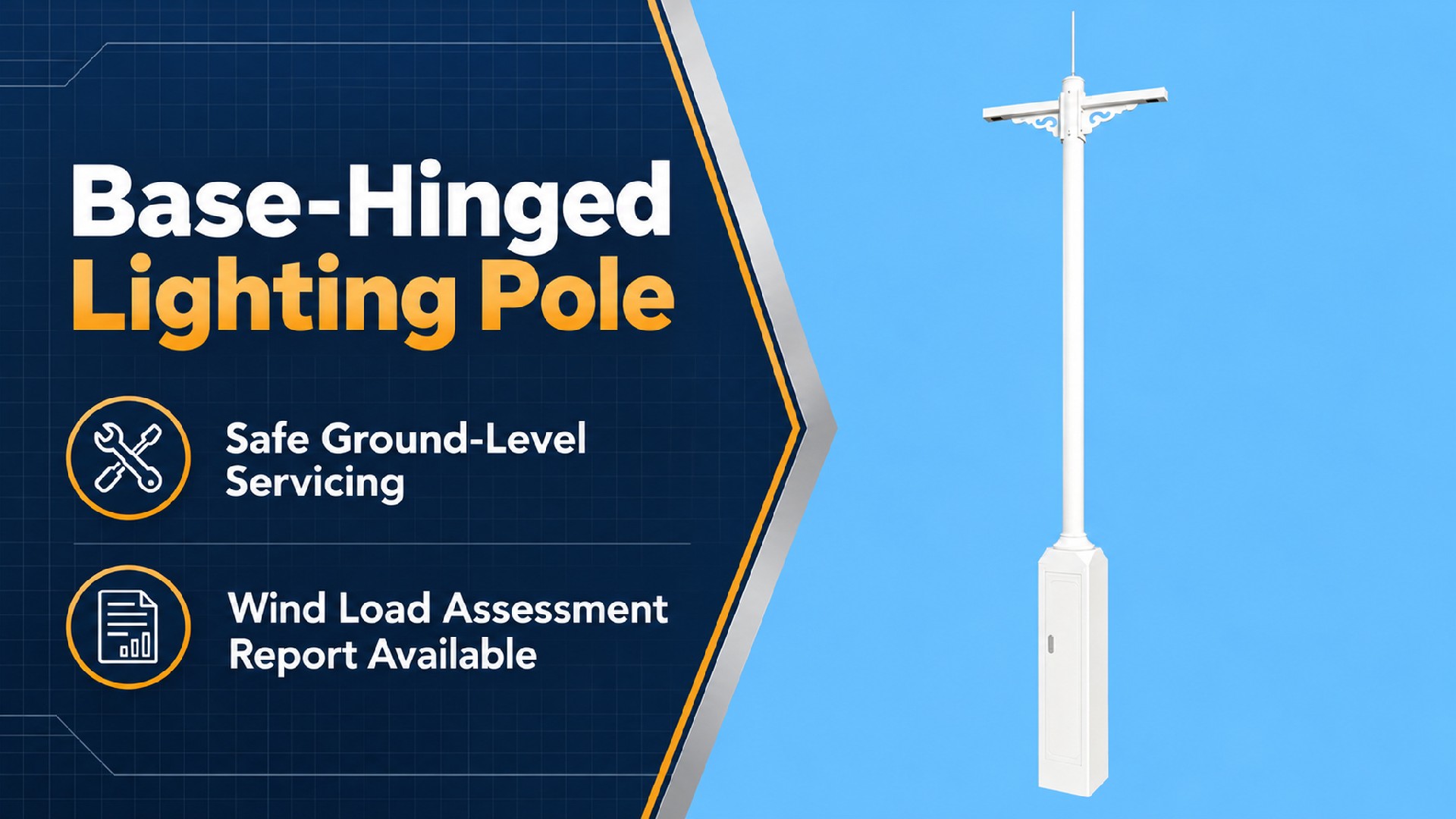
1. Reliable Tilting Mechanism
IP65-sealed enclosed gearbox combined with self-locking worm gears, high‑tensile stainless steel wire rope with a minimum 8‑times safety factor based on minimum breaking force, and a mechanical safety pin lock. Designed for a 15-year operational life with dual independent safety layers, eliminating outdoor corrosion seizure and unexpected boom-up risks.
2. Ground-Level Maintenance
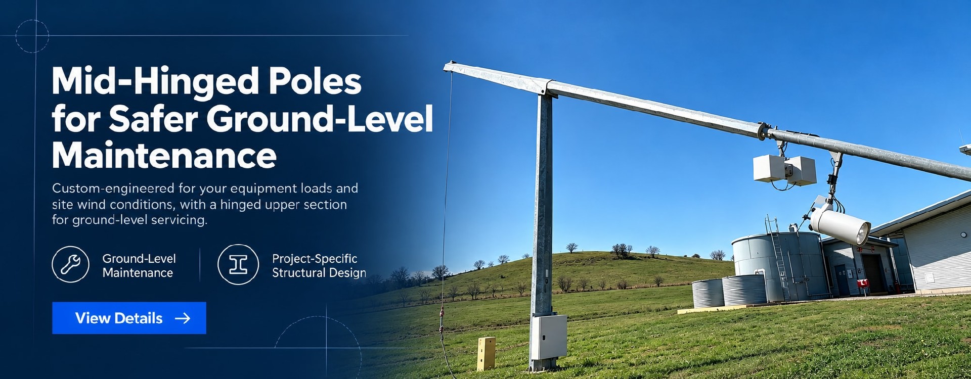
Gear-driven winch mechanism enables 1–2 operators to lower and raise the pole safely from ground level. All luminaire servicing is performed at grade, eliminating the need for aerial work platforms, certified height-access personnel, or traffic control.
3. Batch Consistency
Fully CNC-controlled production and rigorous SOPs ensure uniform wall thickness, flange flatness, and coating thickness across entire batch orders for zero on-site modifications. Includes reinforced flanges (2–4 mm thicker than standard fixed poles) with stiffener ribs engineered to withstand additional bending moments from the tilting system.
4. End-to-End In-House Manufacturing
Complete vertical integration—spanning raw steel procurement, CNC cutting, bending, welding, mechanism machining, hot-dip galvanizing, and powder coating helps us offer competitive ex-works prices against comparable manufacturers.
| Metric | Details |
| Tilting mechanism type | Gear drive + winch (manual/motorized optional) |
| Mechanism design life | ≥15 years (under normal maintenance) |
| Locking mechanism | Worm gear self-lock + safety pin mechanical hard lock (dual independent safety layers) |
| Factory function test | Every pole undergoes a full-function tilting cycle test before shipment (lower / lock/raise) |
| Engineering validation documents | Structural calculation report (tilt-cycle load analysis + hinge joint stress verification) + foundation reaction data package |
| Spare parts supply | Critical mechanism spare parts list provided (gear set/wire rope/safety pin/seals), available with initial shipment or ordered separately later |
Quick jump: Commercial Terms | FAQ | Luminaire Adaptability
| Parameter | Standard Carbon Steel Pole Specification |
| Pole Height | 3 m – 10 m (customizable per project) |
| Material | Carbon steel (Q235B / Q355B,standard), 304/316L stainless steel(custom for corrosive environments), aluminum alloy (6061-T5/6061-T6/6082-T6, custom for low-height & light-load applications only) |
| Wall Thickness | 3mm - 16mm(Customized per height & load) |
| Base Flange | Reinforced type, 2–4 mm thicker than equivalent fixed pole, with gussets(optional) |
| Bracket load capacity | Single arm ≤50 kg; dual arm ≤80 kg |
Wire rope specification | Stainless steel wire rope, ≥8 mm diameter, breaking strength ≥5 tonnes |
Operating personnel | 1–2 persons |
| Tilting cycle time | Approximately 15–30 minutes each way (lower / raise) |
Supported by an ISO 9001:2015 quality management system, we can adapt pole design, manufacturing quality control, corrosion protection, and technical documentation to project-specific standards and local requirements, supporting overseas project approval, procurement, and acceptance.
Structural Design & Wind Load Verification: Structural calculations can be performed in accordance with EN 40 / EN 1993, AASHTO, applicable AS/NZS standards, SASO requirements, or other project-specified codes. Design verification can incorporate site wind speed, equipment loads, mounting height, and environmental conditions.
Welding & Manufacturing Control: Welding procedures and quality control can be adapted to applicable EN 1090 execution requirements and ISO 3834 welding quality requirements, with corresponding process, inspection, and documentation controls implemented as required by the project.
Corrosion Protection: Hot-dip galvanizing and coating systems can be configured according to the project environment and required service life. Treatments can be specified to ISO 1461, ASTM A123/A123M, or other project requirements for standard outdoor, coastal, high-humidity, and high-salinity environments.
Engineering Documentation Support: Project documentation can include structural calculation reports, shop drawings, material certificates, welding records, galvanizing or coating inspection reports, dimensional inspection records, and factory quality documentation for client, consultant, or EPC review.
Multi-Market Project Support: We support project requirements across Europe, North America, the Middle East, and Asia-Pacific. Applicable design standards, inspection requirements, and document packages can be defined according to the project location and technical specification.
Industrial-grade pre-engineered luminaire arms and mounting brackets, precisely matched to mainstream outdoor luminaires from global manufacturers based on your project specifications.
For tilting poles: Luminaire and cantilever loads are incorporated into the overall structural load calculation of the tilting system.
Compatible Luminaire Types:
North American Style Cobra Head LED Street Lights (Standard arm + slip-fitter / clamp mount)
Single / Double Cantilever Roadway LED Luminaires (Top-mounted flange plate)
Area Floodlights (Heavy-duty cantilever bracket)
Post Top / Garden Lights (Top flange plate)
All-in-One Solar Street Lights (Pre-configured mounting positions for PV panel brackets)
🔧 Precision Customization: Arm length, tilt angle, bracket structure, and cable entry points can all be fully customized according to your luminaire specifications or CAD drawings. Arms and brackets feature high-precision laser cutting with dimensional tolerances within ±0.5 mm, with pre-fabrication and anti-corrosion treatments completed entirely in the factory — arriving ready for immediate installation, eliminating on-site cutting or welding that damages protective coatings.
| Recommended Configuration by Scenario | |
Application Scenario | Recommended Specs(H=height) |
| Municipal roads (urban arterial/collector) | H:8–10m, Gear drive+winch (manual), C3-C4 |
| Expressway/freeway | H:10 m, Gear drive+winch (manual/motorized), C4 |
| Industrial park / residential area | H:6–8m, Gear drive+winch (manual), C3 |
| Railway corridor | H:8–10m, Gear drive+winch (manual), C3-C4 |
| Rural road | H:3–6m, Gear drive+winch (manual), C3 |
| Coastal city road | H:6–10m, Gear drive+winch (manual), C5-M |
| Traditional Fixed Pole vs. Tilt-Down Pole — Selection Comparison | |
| Comparison Item | Traditional Fixed Pole/Tilt-Down Pole |
| Recommended height range | Traditional: 3-14 m Tilt-Down: 3-10 m |
| Maintenance method | Traditional: Aerial platform + certified workers Tilt-Down: Ground operation, 1–2 persons |
| Cost per maintenance event | Traditional: High (platform rental + labor) Tilt-Down: Low (standard electrician) |
| Unit purchase price | Traditional: Baseline Tilt-Down: ~20%–35% higher |
| 10-year life-cycle cost | Traditional: High Tilt-Down: Low (maintenance savings) |
| Maintenance safety liability risk | Traditional: Working-at-height accident risk Tilt-Down: Ground-level operation, greatly reduced Mechanism failure risk |
| Mechanism failure risk | Traditional: No moving parts Tilt-Down: Dual-lock design, low failure risk |
| Tilting mechanism | Traditional: None Tilt-Down: Gear drive + winch, mechanical self-lock |
| Best suited for | Traditional: Easy maintenance access, low aerial work costs Tilt-Down: Highways, railway corridors, road medians, remote roads, areas where aerial platform mobilization is difficult or costly |
Selection guidance: If your project involves locations where aerial platform mobilization is difficult, traffic control costs are high, or maintenance frequency is elevated (e.g., tunnel portals, bridge lighting), the tiltable pole is the preferred choice. If maintenance access is convenient and aerial work costs are low, the traditional fixed pole is more economical.
1. Eliminate Working-at-Height — Dramatic O&M Cost Reduction & Greatly Reduced Safety Liability
With traditional fixed poles, every luminaire failure or circuit inspection requires aerial work platforms, certified operators, and traffic control. These recurring costs often exceed the luminaire replacement itself — and working at height exposes integrators to serious safety and liability risks.
The Tiltable Pole Solution:
①Ground-Level Access: A gear-driven winch mechanism allows 1–2 operators to lower and raise the pole entirely from ground level.
②Unskilled/Standard Labor: All maintenance is performed at grade, eliminating the need for certified height technicians, scaffolding, or traffic management permits.
③Foolproof Mechanical Safety: The pole features an independent dual-lock system (worm gear self-lock + mechanical safety pin lock) in the lowered position, minimising risk of unexpected boom-up during servicing.
④Rapid Turnaround: The entire lowering, servicing, and raising cycle takes about 30 minutes.
| Life-Cycle Cost Comparison (Example: 8m pole, 100-pole project, 10-year maintenance lifecycle) | |
| Comparison Dimension | Traditional Fixed Pole / Tilt-Down Pole |
| Initial Capital Expenditure (CAPEX) | Traditional: Baseline Tilt-Down: ~20%–35% higher |
Maintenance Labor & Equipment Cost | Traditional: High (AWP rentals, specialized crew) Tilt-Down: Low (1–2 general operators at grade) |
| Annual Maintenance Frequency | Traditional: 1–2 times Tilt-Down: 1–2 times |
10-Year Cumulative OPEX | Traditional: High Tilt-Down: Significantly Reduced |
| Operator Safety Risk | Traditional: High (Fall hazard, traffic exposure) Tilt-Down: Greatly reduced (Ground-level execution) |
| Mechanism Liability Exposure | Traditional: None (Fixed structure) Tilt-Down: Minimized (Dual-lock independent safety design) |
Bid Competitiveness | Traditional: Standard Tilt-Down: High Value-Add ("Low OPEX & No Working-at-Height") |
Note: The initial purchase premium is typically fully recovered within 2 to 3 maintenance cycles. Premium varies with pole height, mechanism options, and project quantity.
2. Mechanical Reliability & Full Engineering Validation
Movable mechanical structures introduce failure points — gear seizure, corrosion, wire rope fatigue. In the worst case, hinge or locking mechanism failure can cause pole toppling, exposing integrators to severe liability.
Our Engineering Approach:
①Heavy-Duty Gearbox: Enclosed alloy steel gear train with induction-hardened tooth surfaces, sealed grease lubrication, and IP65 dust/water ingress protection.
②Self-Locking Winch: Cast iron/steel housing incorporating a worm gear self-locking mechanism; the pole cannot descend under its own weight even if the crank handle is released.
③High-Tensile Wire Rope: Marine-grade stainless steel (SS304/SS316L), ≥8 mm diameter, with a breaking strength exceeding 5 tonnes (safety factor ≥8×).
④Robust Hinge Assembly: High-strength alloy steel hinge pins coupled with sealed bearings for smooth, long-term operation.
⑤Redundant Safety Lock: Independent mechanical safety pin engagement when fully lowered.
What this means: Mitigate safety liability risks from tilting mechanism failure. Every pole undergoes full tilt-cycle factory testing with an independent dual-locking system. Hinge structural calculation reports available for bids to validate safety for project owners and strengthen your technical evaluation advantage.
3. Absolute Batch Consistency — 100 Units, Uniform Performance
Multi-component mechanical poles risk inconsistent manufacturing tolerances across large batch orders, leading to varying operating feel or fit issues on-site.
Our Manufacturing Standard:
①Synchronized Production: Pole shafts are processed on the same automated CNC lines as fixed poles (laser cutting → CNC bending → automated submerged arc welding → CNC flange drilling).
②Precision Machining: Critical mechanism components (gears, winches, hinge brackets) are machined on high-precision CNC centers to tolerances within ±0.1mm.
③Factory Acceptance Testing (FAT): Every single pole undergoes mandatory FAT before dispatch, including dimensional checks, coating thickness verification, and a full lower/lock/raise functional cycle test.
What this means: Pole #1 and Pole #100 feature consistent dimensional accuracy and uniform mechanism operation, with factory pre‑commissioning to minimize on‑site adjustment work.
4. End-to-End Vertical Integration — Competitive Cost Structure
A 20%–35% initial price premium over fixed poles must be justified by structural longevity and O&M savings, without hidden markups from outsourced sub-components.
Our Manufacturing Advantage:
①100% In-House Production: From raw steel procurement, CNC cutting, bending, and welding, to gear machining, hot-dip galvanizing, and electrostatic powder coating—all processes are performed within our integrated facility.
②Optimized Economics: Economies of scale absorb mechanism machining overheads, ensuring that the purchase premium reflects genuine metallurgical and mechanical value rather than intermediary distributor markups.
What this means: The purchase premium is recovered within 2–3 maintenance cycles through aerial work cost savings. Every year after that is net savings.
Term | Detail |
| Customization | Supported — MOQ 1 unit |
| Lead time | Standard configuration: 3–4 weeks / Custom-engineered configuration: 4–5 weeks |
| Payment terms | 30% T/T advance · 70% before shipment · L/C at sight accepted |
| Trade terms | EXW: Specify named place FOB: Specify port of shipment CFR / CIF: Specify destination port |
| Inspection support | Third-party factory inspection by SGS / BV / TÜV welcomed |
| Samples | Available — sample cost credited against first production order |
⚡ Galvanic Corrosion Prevention: Carefully match fastener materials. When connecting dissimilar metals, use isolating non-conductive gaskets. (Service option: Pre-installed nylon/EPDM isolation gaskets available upon request).
💧 Drainage & Sealing: Keep base drainage openings unobstructed; hand-hole covers and seals must remain intact. Never bury flange plates underground.
🛡️ Surface Protection: Protect coated, passivated, and brushed surfaces from mechanical scratches during installation. Repair damaged areas with material-matched touch-up treatment: touch-up coating for carbon steel/aluminium coated finishes, local passivation for stainless steel.
🔌 Grounding Requirement: Complete proper grounding and equipotential bonding in compliance with local electrical codes.
🏗️ Foundation Rules: Anchor bolts and concrete foundations must satisfy local wind-load requirements. Erect poles only after concrete has fully cured.
⚙️ Tilting Mechanism Commissioning
①Pre-operation inspection: Confirm gearbox grease level is adequate, wire rope has no damage, and safety pin inserts and removes smoothly.
②No-load test: Complete the first tilt and restore cycle before luminaire installation to verify smooth mechanism operation without binding.
③Lock verification: After lowering the pole, confirm the safety pin is fully engaged and gear self‑lock functions properly (pole will not descend when the handle is released).
④Post-raise inspection: After raising the pole, confirm the locking mechanism is fully engaged, and the flange sits flush against the foundation with no gap.
We provide custom wind-load calculation reports, 2D CAD drawings, installation manuals, and tender technical documents to support your global project approvals and customs clearance.
For general-purpose technical handbooks and safety guidelines, please visit our Download Center→
🚀 Rapid Delivery: Typically ship within 3–5 weeks.
💰 Volume Pricing: Tiered pricing structures available for bulk orders.
📦 Export-Grade Packaging: Moisture-proof and shock-resistant packaging optimized for safe container loading.
📊 Real-Time Tracking: Dedicated project managers providing regular production progress updates.
Q1: Will the tilting mechanism seize up after a few years?
A: The gearbox is a sealed unit with grease-filled lubrication. Under normal operating conditions, the mechanism is designed for reliable long-term operation. We recommend inspecting grease condition every 2–3 years and replenishing as needed. Hinge bearings should be periodically greased.
Q2: Can one person operate the tilt mechanism?
A: Poles up to 6 m can be tilted by a single operator under rated top‑load conditions. For 8‑10 m poles, we recommend 2 trained operators.
Q3: Could the pole unexpectedly spring back up when lowered?
A: No. The lowered position is secured by a dual locking system — worm gear self-lock (pole cannot descend under its own weight when the handle is released) + safety pin mechanical hard lock. These two safety layers function independently; either one alone is sufficient to prevent unexpected pole movement.
Q4: How often does the winch wire rope need replacement?
A: The stainless steel wire rope has a long service life in normal outdoor conditions. We recommend visual inspection of the rope surface (checking for broken strands, wear, or corrosion) during each maintenance event. Replace if any abnormalities are found. Specific replacement intervals depend on usage frequency and environment.
Q5: How much more does a tiltable pole cost compared to a fixed pole?
A: The unit purchase price is approximately 20%–35% higher, with the premium coming from the mechanism components (gearbox, winch, hinge bracket, wire rope), material, and machining costs. The premium is typically recovered within 2–3 maintenance cycles through aerial work cost savings — every year after that is net savings.
Q6: How are spare parts for the tilting mechanism supplied?
A: We provide a spare parts list for critical mechanism components (gear set, wire rope, safety pin, seals, etc.), which can be shipped with the initial order or ordered separately during the project's operational phase. Standard spare parts lead time is 1–2 weeks.
Q7: Do you provide technical support if the mechanism develops a fault?
A: We offer remote technical support via video/phone. On-site engineer support can be arranged upon request (travel fees apply). Quality-failed mechanism components are free to replace within warranty. After warranty, spare parts are available at production cost.
Specifications are typical values for reference only under standard conditions — not a guarantee. Final performance shall be determined by project design calculations and factory test reports. Consult a local engineer before specifying.